QuinLED Dig-Octa System
Brainboard-32-8L v4
Specifications
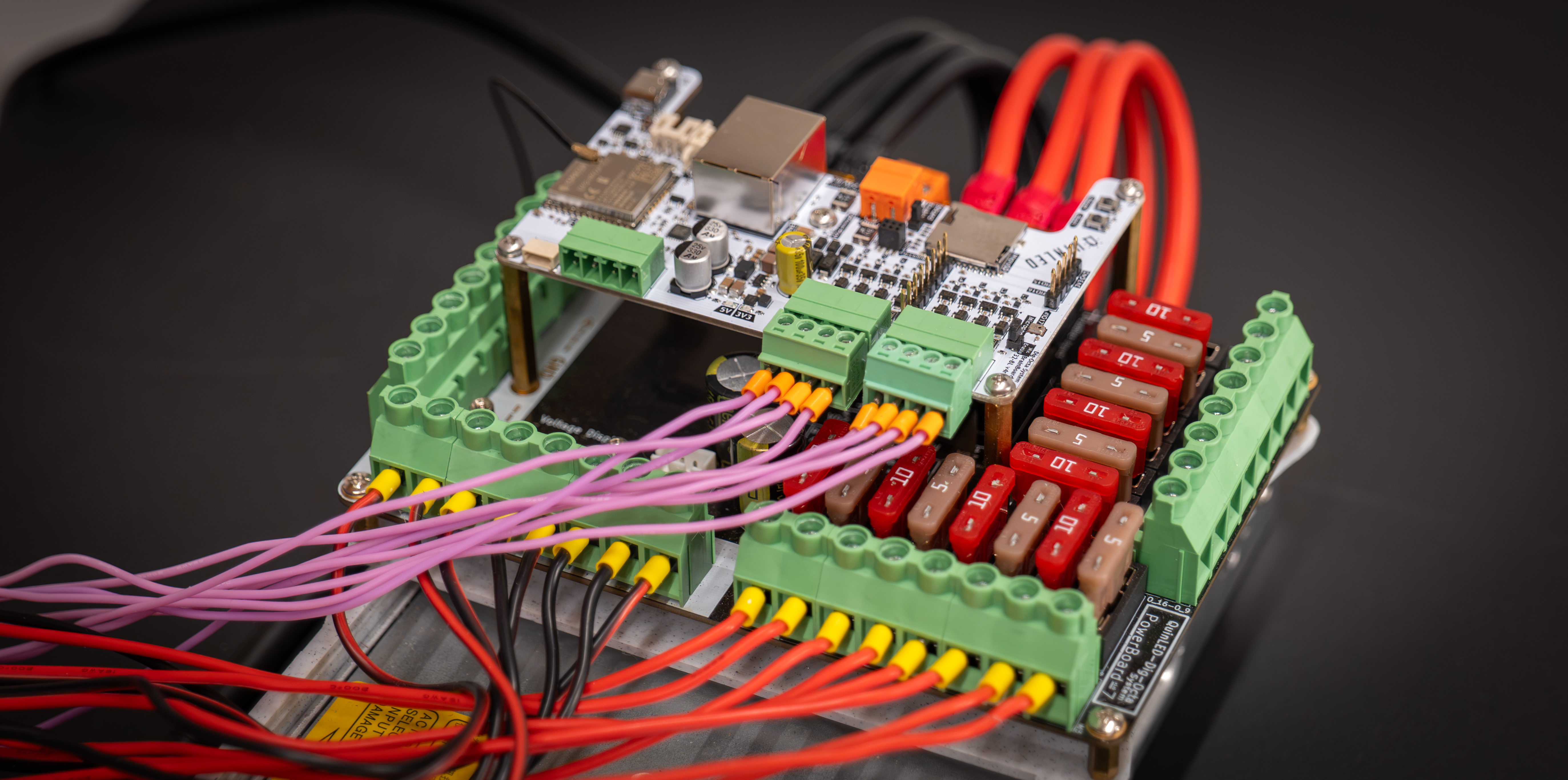
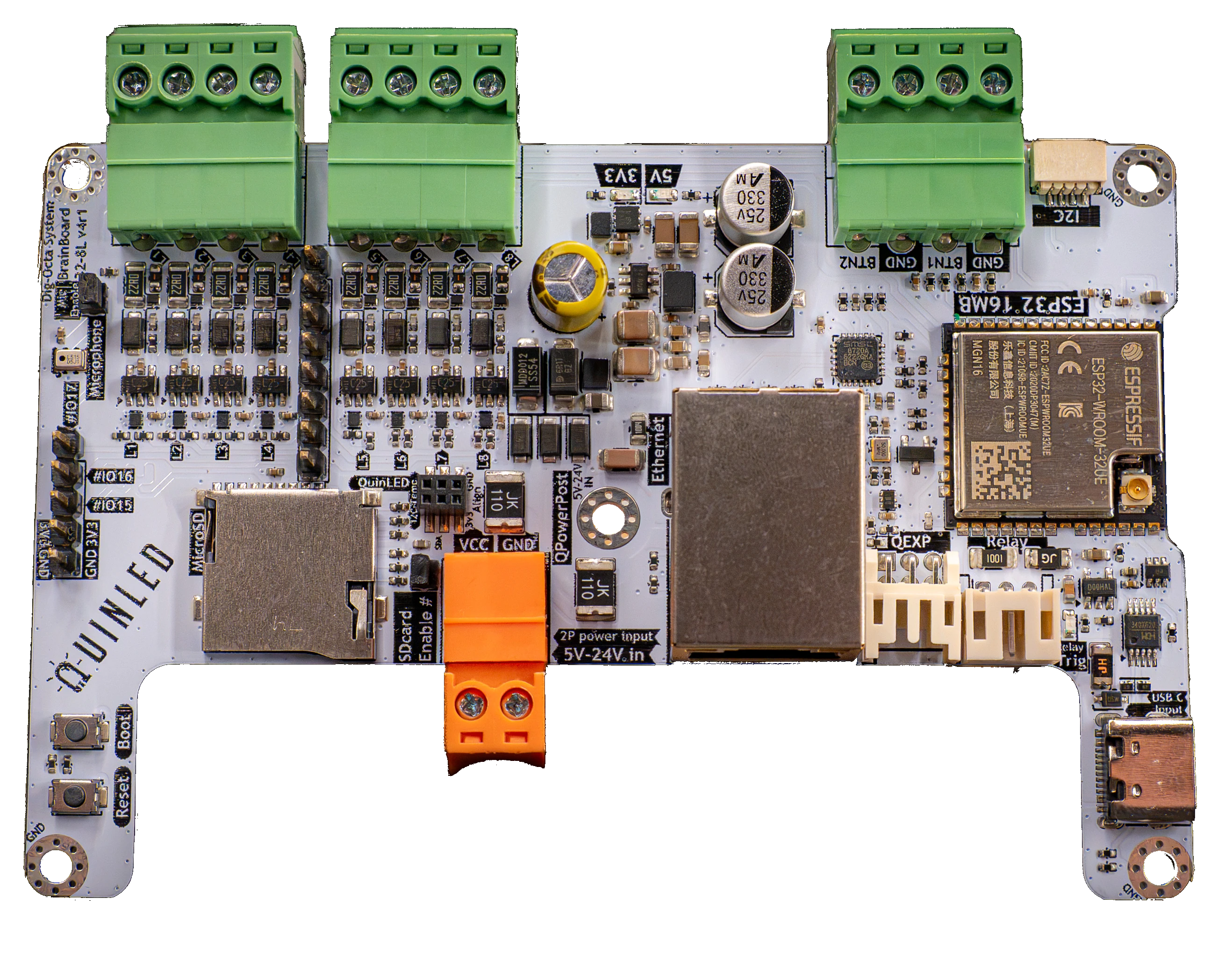
The QuinLED-Dig-Octa Brainboard-32-8L v4 is the first brainboard in what is set to become various brainboard versions in the future. The brainboard is the brain of the Dig-Octa system providing LED outputs and various networking such as WiFi and Ethernet. It also has an I2C connector, button inputs a digital microphone, everything you need to drive the logical side of your LEDs while a powerboard handles the power side!
Design Goal
The QuinLED Dig-Octa Brainboard-32-8L v4 is based around the Espressif ESP32 micro-processor which has been on the market for a few years. This ensures good support for it in WLED, Moonlight and various other software while at the same time having plenty of horsepower and memory to output data lines for a decent number of LEDs.
Specifications
- Based around Espressif ESP32-WROOM-32UE
- Dual-Core 240Mhz microcontroller
- 520 KB SRAM with 16MB of Flash Storage
- WiFi (2.4Ghz 802.11N) and Ethernet capabilities
- Built-in WiFi + Ethernet
- The board can be used over WiFi using an external antenna connection
- Comes delivered with the board!
- Ideal for use in enclosures or when longer range is required
- Onboard RJ45 10/100Mbit Ethernet provided by the LAN8720A chip
- Very stable connection and able to handle real-time pixel data much better then WiFi
- The board can be used over WiFi using an external antenna connection
- SDcard reader
- Onboard SPI connected MicroSD card slot
- Onboard microphone
- Using a high-quality digital I2S PDM microphone
- I²C ports
- I²C port
- Stemma QT/JST SM 1.0mm
- I²C port
- 3x simultaneous power-in connections
- 5V USB-C
- Includes onboard CH340 USB-to-Serial for programming
- Auto-reset to program mode circuit on board
- 5V-24V 2p 3.81mm pluggable connector
- 5V-24V QPowerPost power feed
- 5V USB-C
- Dedicated relay output terminals
- 5.12V out, GND and Relay trigger (5.12V) available on dedicated relay port (pig tail included)
- v4 uses a load-switch to trigger on and off
- Compatible with High or Low trigger relay boards
- v4 uses a load-switch to trigger on and off
- Dedicated Relay on/off LED (blue)
- 5.12V out, GND and Relay trigger (5.12V) available on dedicated relay port (pig tail included)
- 2x input button/switch terminals
- HW debounced and pulled-high to 3.3V
- Including 2x GND terminal to attach the other side of the switch/button to
- 5p pin-headers
- For attaching other accessories
- QEXP port
- 6 pin port with 3V3, GND and 4x GPIO
- Pigtail from port to female dupont included
- Boot/Reset buttons available
- For manual control of the board
- 5x M2.5 board mounting holes
- Outer are 4x GND
- Inner is VCC in (only)
LED features
- 8x level-shifted LED data output channels
- Each channel is level-shifted individually
- A channel failing doesn’t affect others
- Full ESD and OverVoltage protection per channel
- Handles up to a 48V dead short
- ESD protection for lightning strikes and other external influences
- 2x 4p 3.81mm pluggable terminals
- New circuit that doesn’t require resistor-switcher anymore
- Performs as well as “33R” mode for bundled cables
- Also performs well with non-bundled cables
- “Hardware driven” using ESP32 RMT device channels
- Each channel is level-shifted individually
- New “top board” expansion header
- 8p 2.54mm pin header for top expansion boards
- Channel duplication, Diff-Solo outputs, Diff-Adv outputs, DMX in/out, etc. (to follow in the future!)
- 8p 2.54mm pin header for top expansion boards
Specials
- Compatible with Dig-Octa QPowerPost
- Allows powerboard power to be shared with brainboard
- No wires to brainboard needed!
- Fully mixed voltage powerboard stack compatible
- Allows powerboard power to be shared with brainboard
- Renewed DC-DC circuited, 5V-24V compatible
- Provides 3.3V and 5.12V for the brainboard (for onboard electronics, relay and data signals only! Not your LEDs)
- All inputs designed with protection circuits
- Fully allowed to use multiple power inputs at the same time with mixed voltages
- Designed to provide stable power even when switching on/off various power sources (auto switches between inputs while staying online)
- For instance when using the relay feature to turn off LED power supply to powerboard and keeping the brainboard online using 5V USB-C
- Load-switch based relay output circuit
- Provides 5.12v out independent of input voltage
- Board design
- Shape is designed to be fit on top of a powerboard while keeping power input and output fuse + terminals available
- Designed with stackability in mind, all ports remain usable even when stacked
Shared resources
Sadly the ESP32 doesn’t have an unlimited amount of GPIOs available. Because of this on this board:
- SDcard pins are shared with various other functions on the board (I2C lines and QEXP lines)
- This means you will have to choose between either feature on this board
Suggested handling capabilities
Although the ESP32 can handle a good amount of LEDs it’s capabilities are limited. The suggested max amount of LEDs per board are also partly dependent on the software you are running on the board. Please see max LEDs per data channel and FPS here.
- WLED
- For WLED a max total of ~2000 LEDs divided over the 8 output ports is suggested
- ESPixelstick v4
- For ESPixelstick a total of ~3000 LEDs divided over the 8 output ports is suggested
- ESPixelstick is much “lighter” firmware and it handles the processing of the LED data differently allowing a bit more performance
- For ESPixelstick a total of ~3000 LEDs divided over the 8 output ports is suggested