QuinLED-Dig-Octa Example Stacking configurations
With the Dig-Octa system you can build lots of different configurations since you are allow to stack both powerboards and brainboards in various configurations!
Some guidelines:
- Inner M2.5 hole is VCC
- Brainboard input only (hardware protected)
- Powerboard output only (hardware protected)
- Outer M2.5 holes are GND
- All M3 holes are GND
Desktop usage
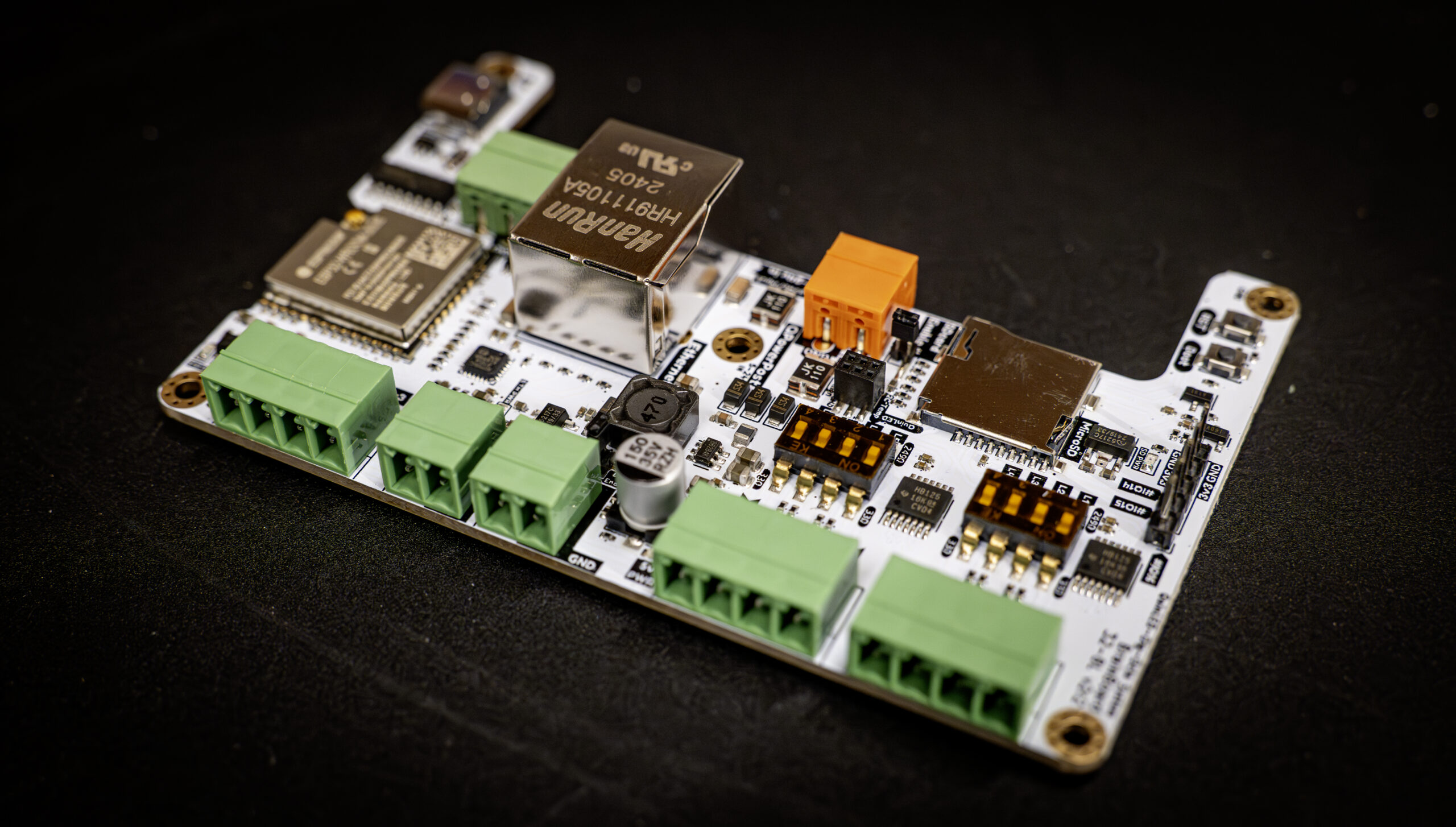
Brainboards
Brainboards have been specifically designed to be fully stackable while all input and output ports remain available.
A Single Brainboard
Although the brainboards have been designed to be used in a stacked configuration with a powerboard there is nothing wrong with using one (or multiple) brainboards standalone if you wish to do all the power distribution and fusing yourself.
The brainboards have 5x M2.5 screw holes in the boards to mount them. The 4 outer holes are connected to GND while the inner hole is connected to VCC which is used in the QPowerPost feature to get power to the brainboard from a powerboard.
For use in desktop or standalone mode you use 4x of the included M2.5 1cm high standoffs with the screw thread on the bottom and 4x screws in the top through the board. For these use only the outer M2.5 holes! This lifts the board nicely off the surface.
The inner M2.5 hole is connected to VCC IN (hardware protected), you can connect this hole to the other boards too but without a powerboard in the stack they will functionally do nothing.
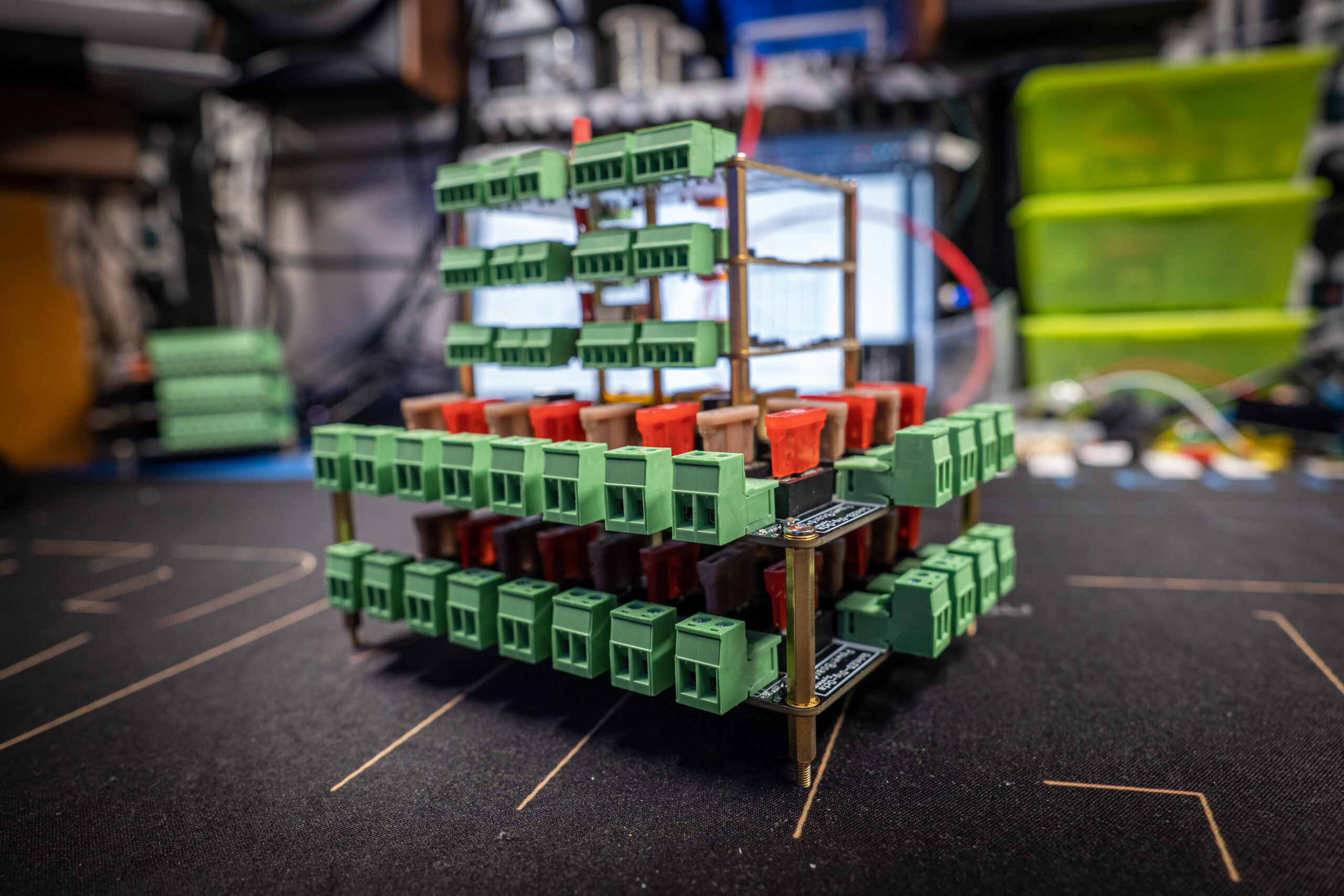
Multiple Brainboard stack
If you require more LEDs, more channels or different features it’s possible to stack brainboards together! This changes the configuration slightly.
For this you again put the 4x M2.5 1cm on the bottom side for the 4x outside holes but this time with the screw portion facing upward, poked through the board. Then you take the included 4x M2.5 3cm posts without any screw thread and thread those onto the portion that is poked through the board. Last, on the top board you screw in the 4x M2.5 screws through the top brainboard and this way you have strongly linked together set of boards!
The inner M2.5 hole is connected to VCC IN (hardware protected), you can connect this hole to the other boards too but without a powerboard in the stack they will functionally do nothing (power input it blocked from a brainboard to the stack).
Stacking on more
If you wish to stack on more then 2 boards, just take out the 4x M2.5 screws and screw in the 4x M2.5 3cm posts with 6mm screw portion and screw these into the posts below (with the brainboard in between). Then add the top brainboard and use the 4x M2.5 screws to screw it in! This way you could theoretically build an “unlimited” stack!
Powerboards
In the current Dig-Octa System line up there are 2 powerboards, the Power-5 and Power-7. Each have their own pros and cons listed below.
Power-5
Power-5 was designed with stackability fully in mind! Because of this it has 12x plug-in style power output connections which can be reached from 2 sides (one side has 8 another side has 4).
Only the input power terminals are not stack compatible so when adding a board to a stack you need to screw these in first (or it needs to be the top board).
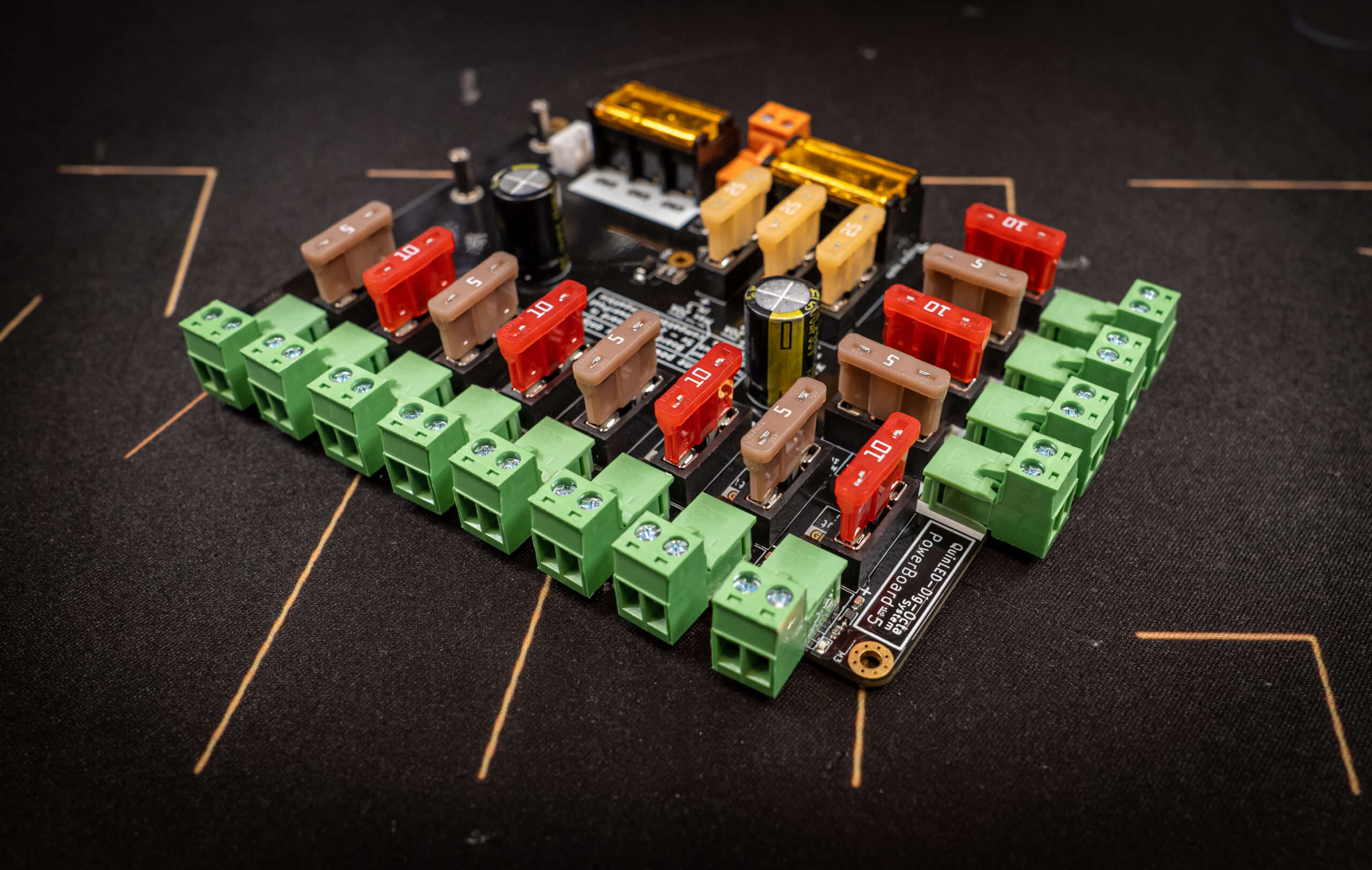
Reachable fuses
The fuses on the Power-5 can still be grabbed when the board is either combined with a brainboard or built into a stack with multiple powerboards, a tool can make it easier to grab the fuses but since the terminals are relatively low height it should be no problem replacing them. All powerboards also have a failed fuse indicator light allowing you to easily identify which fuse has failed.
Power-7(HC)
Power-7 was designed with some other targets in mind (port density, cable size, etc.) and because of such it uses normal screw terminals for the output terminals. If a Power-7 is part of your stack you will need to either make sure it’s always the top board (so all screws can be reached) or that you have screwed in all wires you wish to use before adding the board to your stack.
If you are building a LED box which for instance has xConnect connectors on the outside this limitation might be less important since you’ll rarely have to change anything on lower boards once installed.
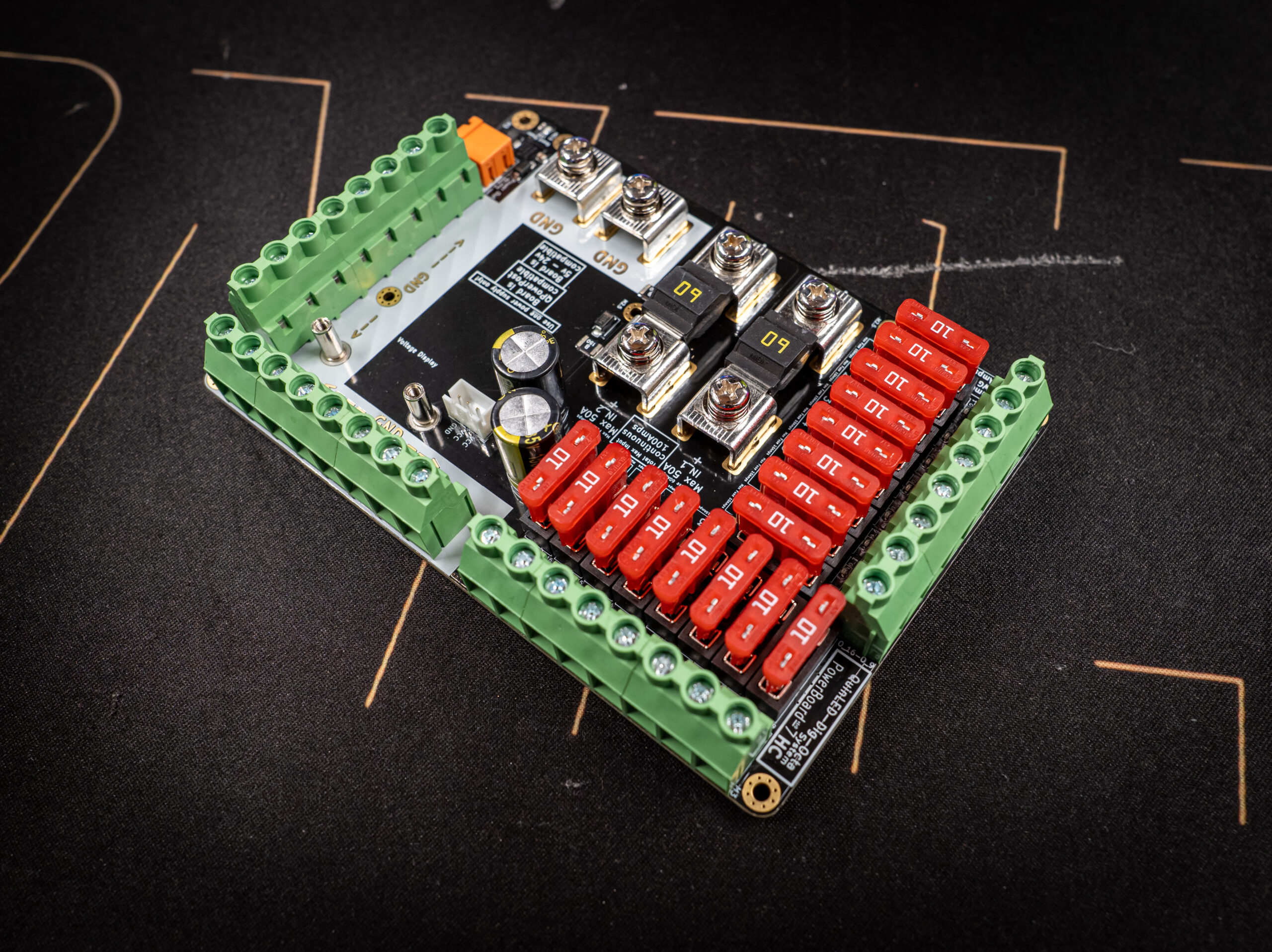
Un-Reachable fuses
The Power-7 both has the fuses much closer together and has terminals that are higher then the fuses itself making it basically impossible to get the fuses in or out when there is a board mounted above it. It is however no problem taking the fuses out if the power-7 is the top board. A brainboard (stack) does not obstruct the fuses!
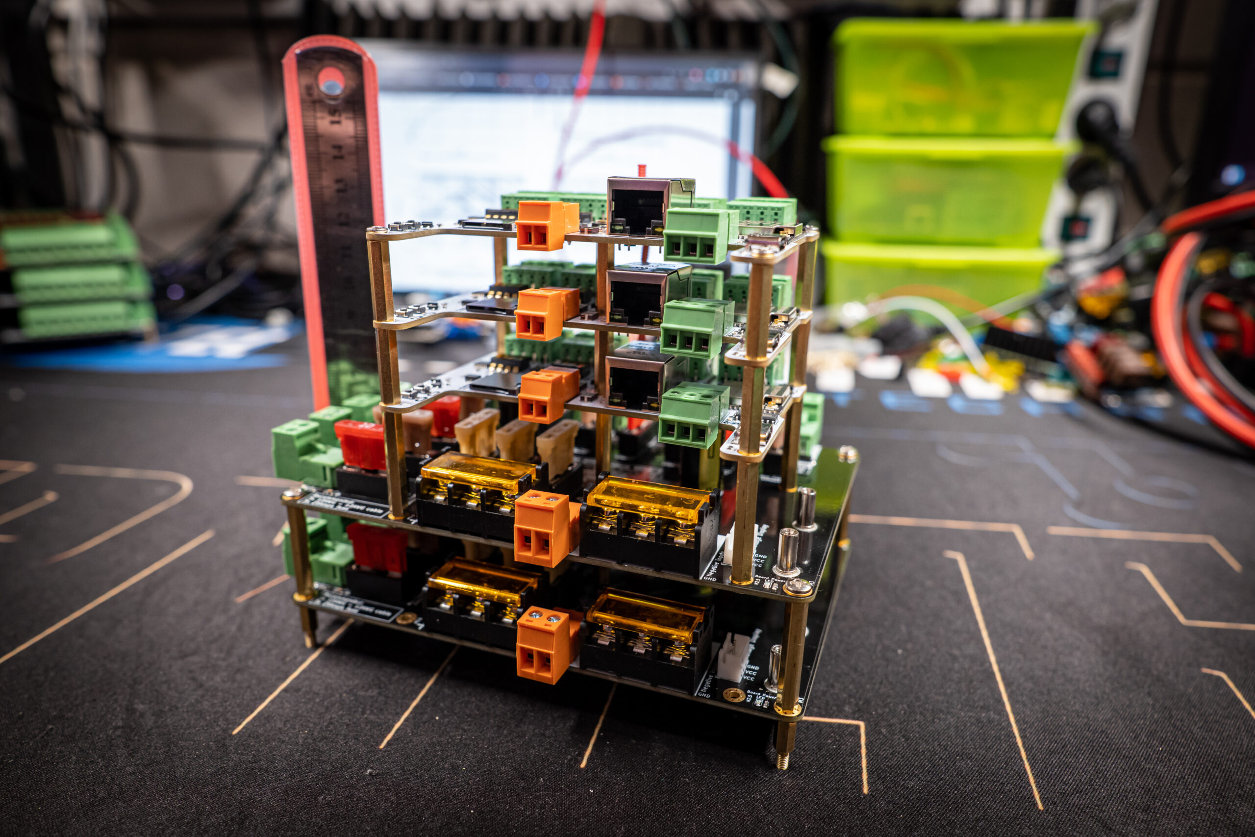
Powerboard and Brainboard stack examples
The true power of the system is when one or more powerboards and brainboards are combined together in a stack. Although each component has limited resources in regards to performance or power, combined they can scale up to be a very powerful system!
Below are some example configurations
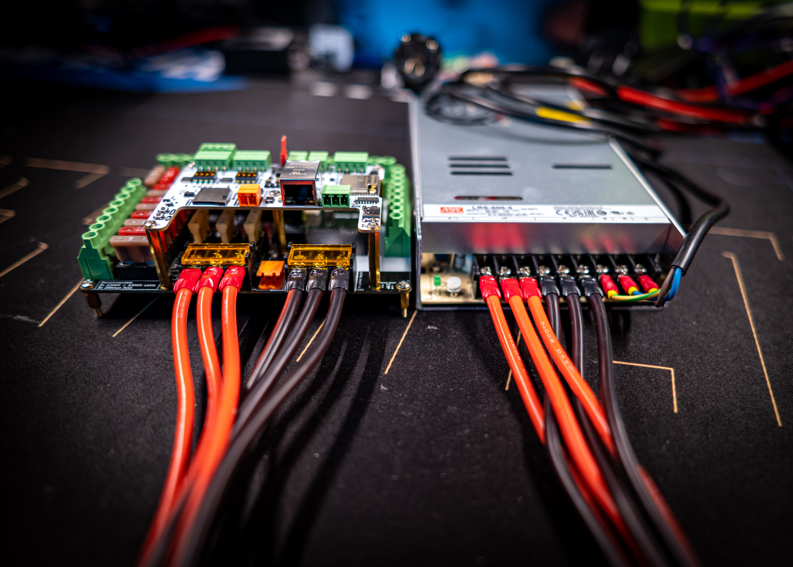
1x brainboard + power-7(HC)
Configured with 1x brainboards and 1x a power-7 the whole becomes a relatively compact system that can drive over *SEE THIS ARTICLE* amount of LEDs with good performance while also having the ability to provide power to them. This can be mostly seen as a “single controller” configuration above what the more compact Dig-Quad can offer.
In this configuration we will be using the QPowerPole feature to power the brainboard(s) in the stack. This feature is compatible with 5v, 12v and 24v main power supplies. Please see limitations that might apply here.
To build this stack for desktop usage you do the following:
- Take your powerboard and the 4x M3 1cm posts it comes with. Oriented it so the posts are beneath the board with the 6mm screw threads on the bottom then use the 4x M3 screws through the top of the board. This gives a stable base for the board to sit on, slightly above any surface
- If you are using a Power-7HC it’s suggested to screw in your power input wires and fuses now. If you are using a Power-7 it’s no problem screwing in the power input wires later
- Take 5x M2.5 3cm posts which have a screw hole on both sides
- Hold screw on the bottom side of the powerboard and poke it through one of the 5x M2.5 holes and then thread in the post with the other hand. Do so for all 5x posts (4x outside and 1x middle of the brainboard)
- Once all are in, take a screw driver and while holding the post slightly tighten the screws on the bottom side of the powerboard, do not use too much force, slightly hand tight is fine
- After that, take your brainboard, put it on top of the 5x posts and screw in the second set of 5x M2.5 screws until they are again slightly hand tight
- All done!
This gives you an 8x LED data port configuration with 16x power ports available with either 50Amps or 100Amps (Power-7HC) continuous of power.
2x brainboard + power-7(HC)
The above setup can easily be expanded to have 16x LED data ports while keeping the 16x power ports (for when no injection is needed for instance when running 16x 100 LED props).
To accomplish this do the following after the above configuration:
- Unscrew the top 5x M2.5 screws
- Take 5x M2.5 3cm posts with 6mm screw thread and hand thread those through the brainboard that had the screws in it previously
- Add the second brainboard on top of the pillars and screw in the 5x M2.5 screws
- All done!
Multiple brainboards and multiple powerboards
With the above examples you should be able to piece together how to create a stack of brainboards and/or powerboards. Even with this configuration as long as a single powerboard is receiving power, all brainboards will automatically be fed with power! Please see the general stacking rules article for more information!