QuinLED-Hybrid-Hexa pinout guide
Back to QuinLED-Hybrid-Hexa index
To be able to configure the QuinLED-Hybrid-Hexa in your software of choice (like WLED or ESPhome) you are going to need to know what is connected to what pins. In the below table you can see exactly how all the hardware is connected internally.
| Board | GPIO | Use |
|---|---|---|
| Button_1 | GPIO_36 | Button/Switch/Sensor connection (Pulled High, HW Debounce) |
| Button_2 | GPIO_39 | Button/Switch/Sensor connection (Pulled High, HW Debounce) |
| Button_3 | GPIO_34 | Button/Switch/Sensor connection (Pulled High, HW Debounce) |
| I²C SDA | GPIO_15 | External I²C connections using Stemma QT/Qwiic connector |
| I²C SCL | GPIO_16 | External I²C connections using Stemma QT/Qwiic connector |
| L1 | GPIO_33 | LED_1 PWM Output (CW) |
| L2 | GPIO_32 | LED_2 PWM Output (WW) |
| L3 | GPIO_12 | LED_3 PWM Output (B) |
| L4 | GPIO_4 | LED_3 PWM Output (G) |
| L5 | GPIO_2 | LED_3 PWM Output (R) |
| Digital LED Relay | GPIO_13 | Power cut for Digital LED positive output |
| Digital LED Data | GPIO_5 | Level-shifted Data pin for LED data |
Ethernet configuration
- In WLED please select “QuinLED-Dig-Octa”
- In ESPhome use the following configuration:
-
ethernet:type: LAN8720mdc_pin: GPIO23mdio_pin: GPIO18clk_mode: GPIO17_OUTphy_addr: 0
-
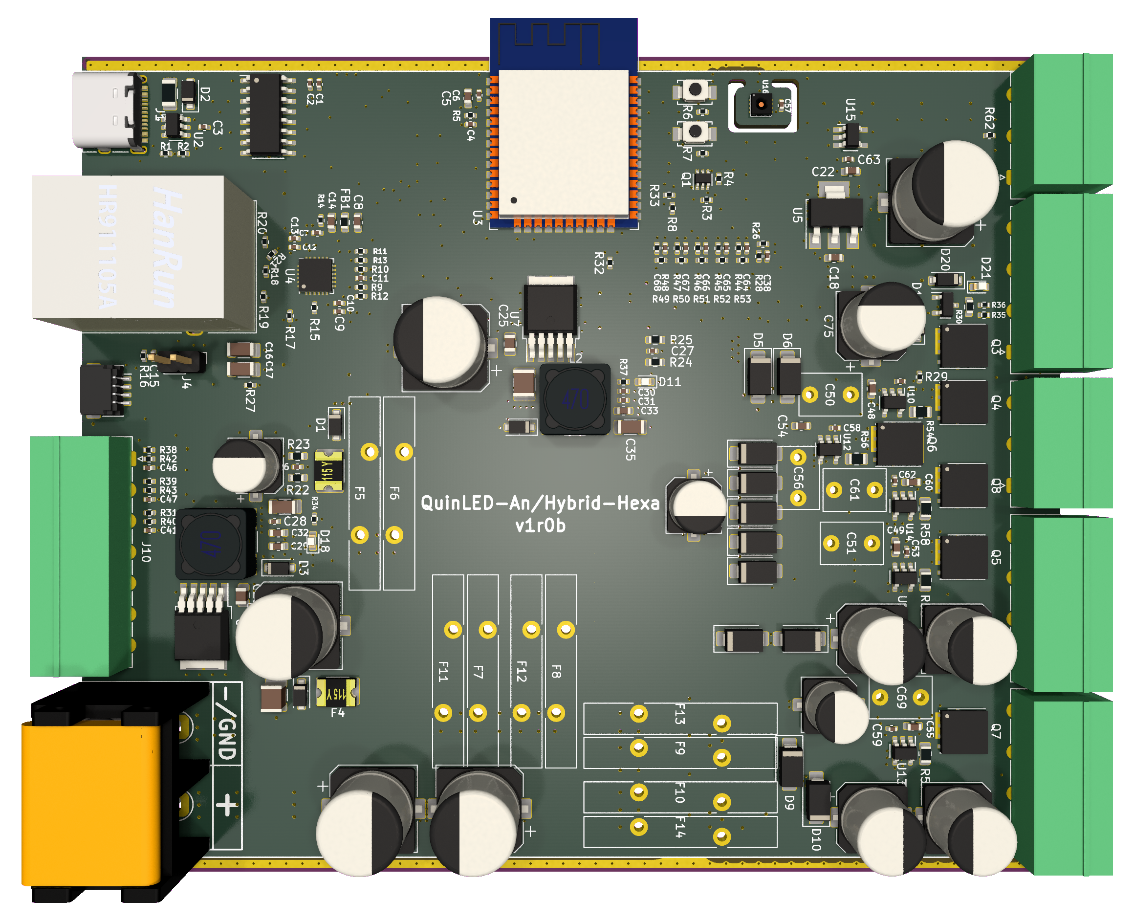
PCB shots
(will be replaced with product shots including casing in the future)