
QuinLED-ESP32 Board Details
The QuinLED-ESP32 custom version is based around the D1 Mini32 form factor that is for sale in a lot of places. It has a few differences though in philosophy and used components. This article will show the board limits and the pinout of the board (which is also labelled on the board itself).
Board Power limits
To try and protect the board from dying a premature death, the board employs two precautions:
- The USB port has a ESD protection chip first, this should protect the onboard circuits from any ESD power spikes.
- There is a PTC fuse which has a “power hold” limit of 750mA
- Generally speaking this should be more then enough to run any normal application
- This also means this board is explicitly not meant for running LEDs or a big load “through” the board. Any load higher then 750mA for a few seconds will trigger the PTC and cut off all the power to the board to prevent any potential damage.
- Generally speaking this should be more then enough to run any normal application
Board Pinout
Pinout tables for QuinLED-ESP32
(Pins in bold represent 2x 8 pins ESP8266 footprint)
Looking from the front:
| 9x Pins row | 9x Pins row | Antenna | 9x Pins row | 9x Pins row |
|---|---|---|---|---|
| GND | EN | TXD | GND | |
| GND* | S_VP / IO36 | RXD | IO27 | |
| S_VN | IO26 | IO22 | IO25 | |
| IO35 | IO18 | IO21 | IO32 | |
| IO33 | IO19 | IO17 | IO12 | |
| IO34 | IO23 | IO16 | IO_4 | |
| IO14 | IO_5 | GND | IO_0 | |
| 3v3* | 3v3 | 5v0 / vIN | IO_2 | |
| 5vF* | IO13 | IO15 |
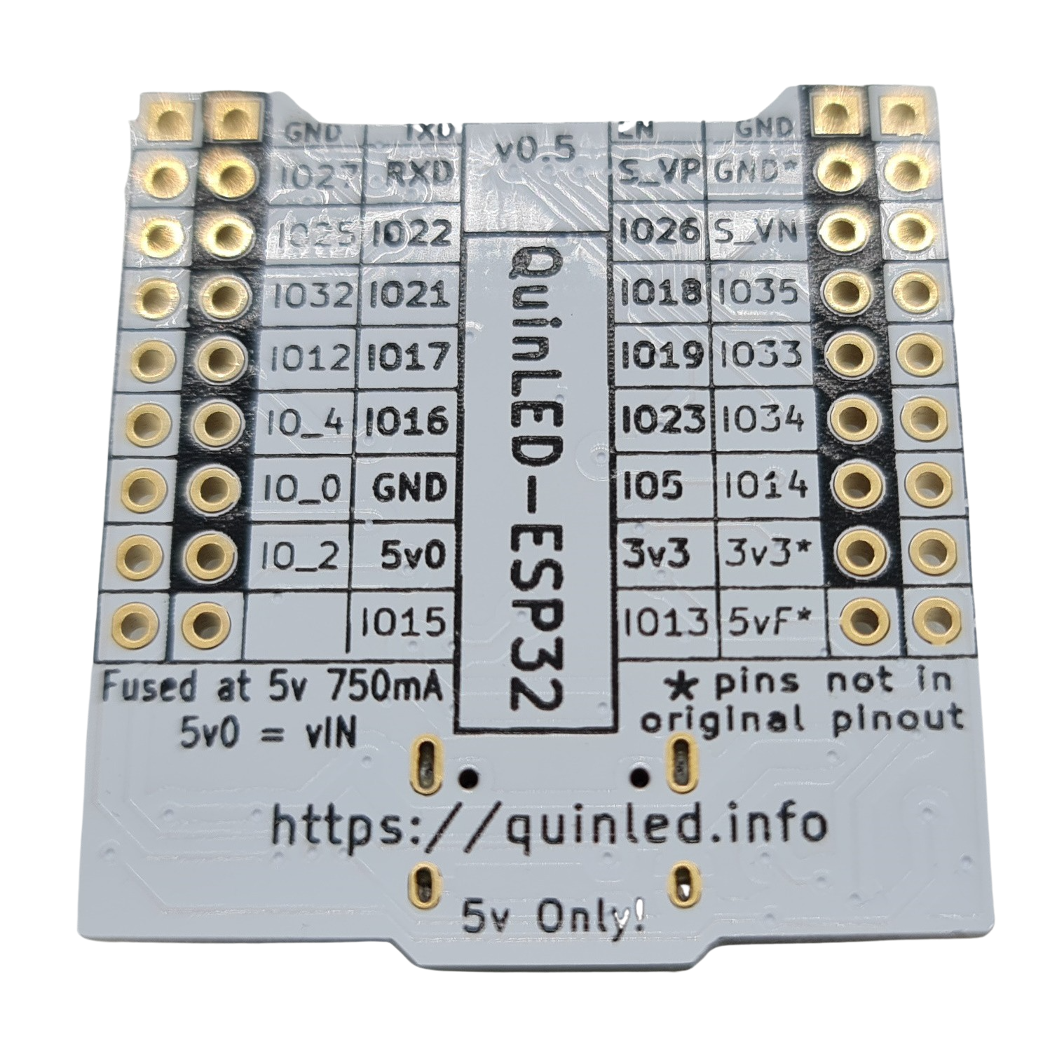
Looking from the back:
| 9x Pins row | 9x Pins row | Antenna | 9x Pins row | 9x Pins row |
|---|---|---|---|---|
| GND | TXD | EN | GND | |
| IO27 | RXD | S_VP / IO36 | GND* | |
| IO25 | IO22 | IO26 | S_VN | |
| IO32 | IO21 | IO18 | IO35 | |
| IO12 | IO17 | IO19 | IO33 | |
| IO_4 | IO16 | IO23 | IO34 | |
| IO_0 | GND | IO_5 | IO14 | |
| IO_2 | 5v0 / vIN | 3v3 | 3v3* | |
| IO15 | IO13 | 5vF* |
Please see the following foto for the pin reference, also as seen from the back
Custom pins
Added Extra Pins
As noted on the board, the pins marked with a * are added over the original Mini32 design. They are either extra or have changed in function.
There are three pins, all in the most right row (looking from the back). These are an extra GND* pin on the top, and a 3v3* and 5vF* at the bottom of the right row. GND and 3v3 are connected to their equivalently named pins but 5vF is unique because it’s run through the onboard PTC to offer extra protection for whatever is connected.
*If you are using this board as a compatible replacement to the normal D1 Mini32 board, it is best to not to connect these pins. Although most boards should not have anything connected to it (and thus causing no problem) you can never be too safe!
4×9 pins, not 4×10 pins!
The board, by design, uses 4×9 pin headers instead of the commonly found 4×10 pins. The pins removed are connected to the internal flash memory of the WROOM ESP32 module and serve no real-world usage, this allowed more flexibility in the design of the board.
Be mindful that when plugging the board into a 10 pin socket you line up the pins at the antenna end of the board. This there will be one free pin on the socket at the USB end of the board.
Pins used for QuinLED-Dig-Uno v2 and QuinLED-Dig-Quad v1
Pins marked in bold on the back or with black border on the front
Pins used for QuinLED-Dig-Uno v3 and QuinLED-Dig-Quad v2
For the newer versions of the boards we recommend to solder all pins so 4×9 pins
End Conclusion
Although this board is tightly integrated with my custom boards I’m selling, they aren’t solely meant for that purpose, they are still general purpose development boards just with my twist on it and some uniquely added features! Without the extra * pins soldered, they are 100% compatible with all other projects out there and perfectly suitable for the project you are doing yourself and might want to have external antenna capability or make use of the Ethernet option!