Quinled-Dig-Quad: Using a power supply relay
Guest article by: ezcGman|Andy !
2023-12 The QuinLED-ESP32 Legacy versions are no longer being offered!
This article is an extension to the QuinLED-Dig-Uno relay article, so I won’t cover the “Why I should do it” part, but instead focus on the wiring specifically for the QuinLED-Dig-Quad. Wiring for the different versions is mostly the same, but there are a few little differences per version.
I will cover parts list and the general concept below. If you already know all that, please use the links below to directly jump to the wirings:
- All versions: Wire the relay and small PSU
- Version 2 & 3, both pre-assembled & DIY
- Legacy / Version 1, both pre-assembled & DIY
IMPORTANT NOTE: Remember we’re working with AC power wires! If you have the slightest doubt in what you’re doing, please get help from professionals! AC wiring can be dangerous!
Parts required and wire overview
Required parts:
- A QuinLED-Dig-Quad 💪
- A relay
- The big PSU for your LEDs
- A 2nd / small PSU to keep the board online. Anything with at least 1A is sufficient here, like an old phone charger
- For simplicity, this article will assume you’re using an old USB phone charger
- For most versions, this needs to be 5V! Check the section for your version below if you can use a higher voltage.
- Wires:
- AC wire for your big PSU
- Additional ~20cm of AC wire
- When saying “AC wire”, check what is usually used for AC wiring in your area, usually 3-core and at least 1,5mm² per core
- USB cable (preferably a “charge only” cable, so it doesn’t have any data wires, which we don’t need and potentially make the GND and positive wire a higher AWG)
- Three wires with female Dupont on one side, or tools to make some
Optional / suggested parts:
- Wire stripper for easier insulation removal
- Fork style wire terminals and crimping tool
- Wire ferrules and crimping tool
- I highly recommend using wire ferrules to make proper and safer connections, especially when working with AC, so you don’t accidentally touch them or the rip out, etc.
Wire overview / Concept
A relay is a switch which we can control using a trigger signal coming from the QuinLED board. Our goal in using it is to completely shut off the big PSU to save a lot of stand-by power. The relay will sit on L / “phase” (usually brown or black) of the AC wire coming from your power socket and from there to your big PSU. So N (usually blue) and Earth (usually yellow/green) will go directly to the big PSU.
As turning off the big PSU will also cut power to the QuinLED board, we need a 2nd small PSU/USB-charger to keep the board alive. This will connect to the green 5vEXT terminal on the QuinLED.
Lastly, we will need to attach power wires to the relay, as it is an active component and last a signal wire to trigger the relay board on and off.
For all versions: Wire the relay and small PSU
This part is the same for any version
First, we gonna wire the big PSU, the relay and your AC wire going to your socket
- Remove ~15-20cm of the outer insulation of the AC wire, so you see three wires inside:
- L / “phase” (usually brown or black)
- N (usually blue)
- Earth (usually yellow/green)
- Crimp the fork style terminal to the N and Earth wire:
- These will go directly to the big PSU.
- Crimp a ferrule to the L wire:
- This will go to the common / “COM“ port of the relay. Check your relays pinout closely, but usually this is the middle of the three screw terminals.
- Now use ~15-20 cm of spare (brown) AC wire and crimp a fork style terminal on the one end (this side goes to the big PSU) and a wire ferrule to the other end (this side goes to the relay terminals). A relay usually has a “NO” and “NC” terminal:
- “NO”: “Normally Open”: The relay is open when it is not triggered / switched. So there is no connection between this terminal and “COM“
- “NC”: “Normally Closed”: The relay is closed when not triggered / switched. So there is a connection between this terminal and “COM“
We will use the “NO” terminal, because we want that our PSU turns on when the relay is triggered / switched, so it makes a connection between “COM“ and “NO”.
Note: If your relay does not clearly state which port is NO and which is NC, you can use a multimeter to find this out: Set it to measuring continuity and tap the middle terminal with one probe and either the left or right with the other probe: The NC terminal will beep / have continuity when the relay is not triggered, the NO will not!
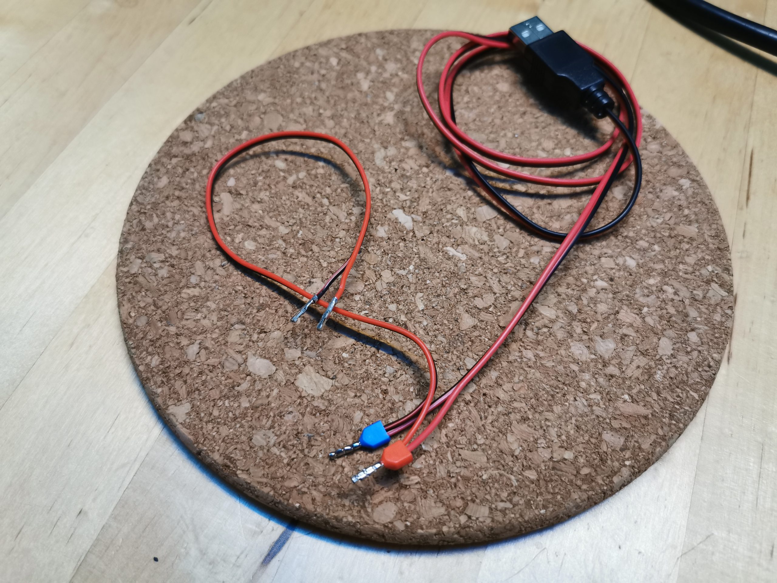
Wiring up the small PSU
Because both the QuinLED board and the relay need 5V standby power, we will both connect them to the small PSU. To do so, snip off the end of the USB cable that’s not going into the charger and remove around 5cm of the outer insulation. This should reveal a red (+5V) and black (GND) wire (if you see more, ignore them and just snip them off (These are the USB data wires)). These will go into the green 5vEXT terminals together with the dupont wires that will power the relay. So twist one of your Dupont wires to each of the red and black wire of the USB cable and crimp them together into a ferrule. Like so:
*If you don’t have the tools for this, screwing the wires in together can also work! Using wire ferrules is a much neater and more secure solution though, so highly recommended!
Screw the ferruled ends of these wires into the green 5vEXT terminals at the front of the Dig-Quad: +5V of the USB to “5vEXT” and GND to GND.
On the other end of those wires you now have the two female Dupont connectors.
- Check your relay:
- It should have a 3-pin header. Closely check the wiring for it and stick the two loose wires into a 3-pin Dupont plug according to the wiring on your relay:
- There should be a pin called “+5V” or “VCC”: This goes to +5V from your USB charger and GND goes to GND, obviously.
- Now also take your 3rd Dupont wire and stick it into the remaining port of the 3-port Dupont plug
- This will be the trigger signal and should read “IN” or something similar on the relay. Leave the other end unconnected for now, this will be connected in the version specific articles below, so let’s continue there.
- It should have a 3-pin header. Closely check the wiring for it and stick the two loose wires into a 3-pin Dupont plug according to the wiring on your relay:
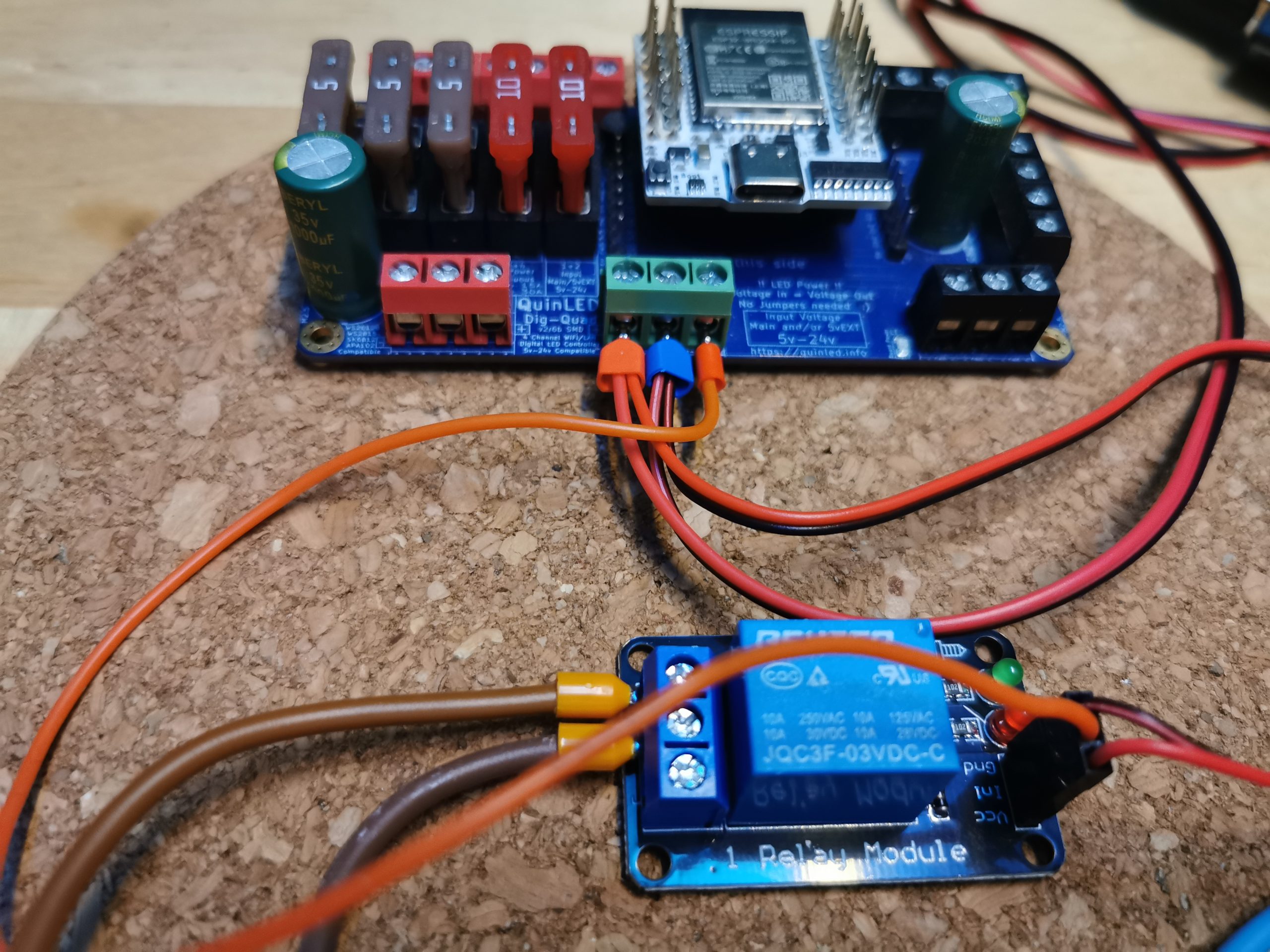
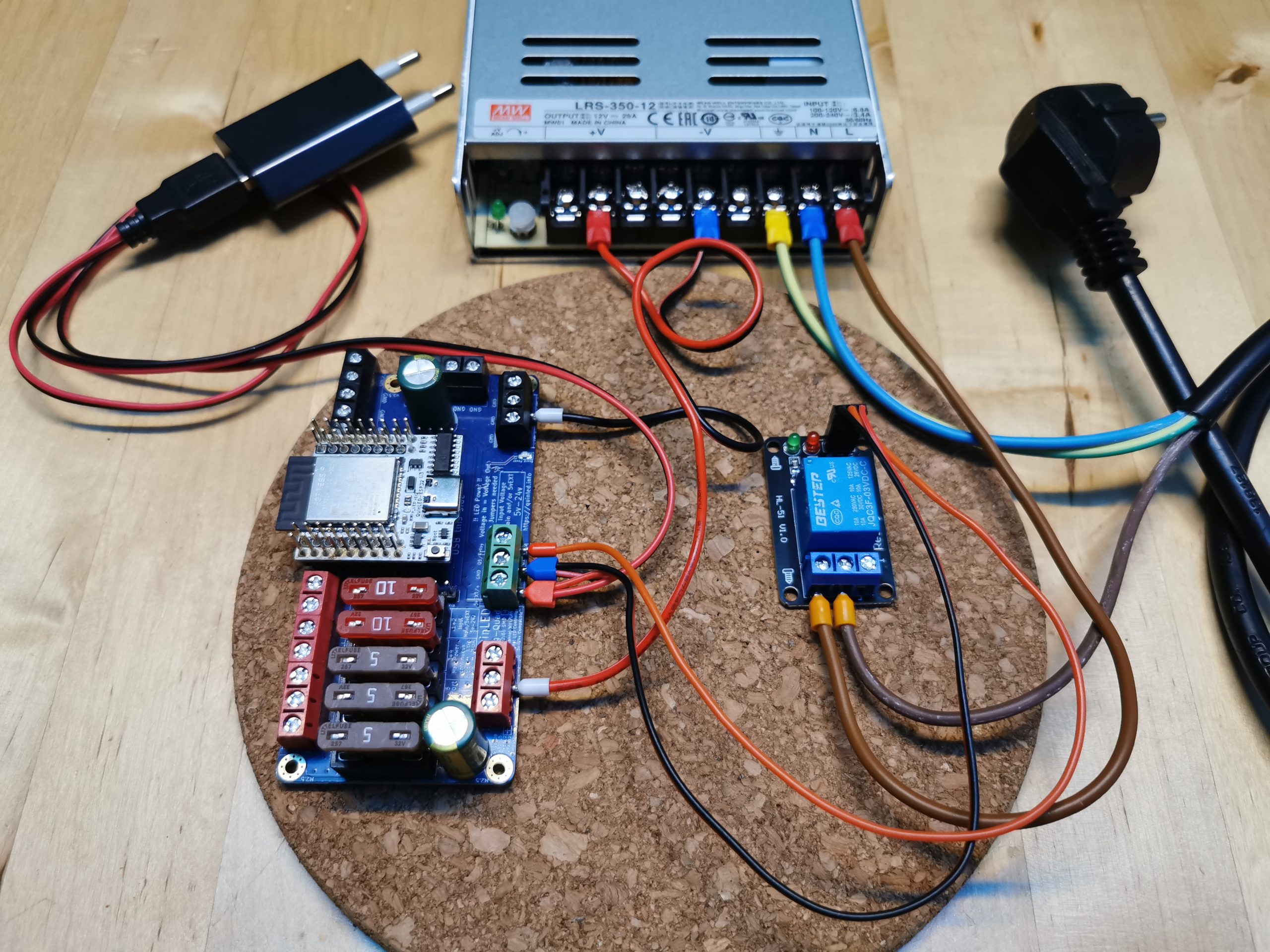
You should now have this setup in front of you (note the Dig-Quad can look different depending on which version you have):
Dig-Quad version 2 & 3, pre-assembled & DIY
(Version 3.1 is the current pre-assembled version and v3 for the DIY version at the time of writing this article!)
Since version 2, the Dig-Quad features a 3-port terminal at the front, that makes wiring a relay a little more easier: The trigger signal for the relay can be obtained from this terminal directly! (This terminal also outputs a higher 5.12v trigger signal vs the normal 3.3v one!)
So take your third Dupont wire and screw this into the “Q1R/Relay” port of the green terminal at the front, so it looks like this:
Special case for v3 *DIY only*: Make sure to set the jumper right next to the green terminal correctly. This picture will show you the options for the jumpers.
The pre-assembled versions don’t have any jumpers for anymore; they have auto-voltage detection! 🙂
Remember for later / WLED: Our relay GPIO will be 15!
That’s already it: Wiring the relay is done, let’s continue with setting up WLED below.
Dig-Quad version 1, pre-assembled & DIY
(This is called the “legacy” version)
Wiring a relay to the first ever version of this board is very similar to the later versions with just a little key difference: It only has a 2-port screw terminal at the front for positive and GND of the small PSU, but not for the trigger signal, so we need to get this from a pin header. You can choose either Q1-Q4 for this, we will use Q1 in this guide.
So take the unconnected end of your third Dupont wire and connect it to Q1 on the Dig-Quad (it’s right next to the ESP-32 socket) so it looks like this:

Important: Also make sure to set the jumper above the green terminal correctly to “5vEXT”!
Remember for later / WLED: Our relay GPIO will be 22!
That’s already it: Wiring the relay is done, let’s continue with setting up WLED below.
Configuring WLED
Last step is configuring WLED, so it will actually trigger our relay when we turn our LEDs on or off.
Open WLED, click on “Config” => “LED Preferences” and find the setting for “Relay GPIO”. Set this to the GPIO depending on your board version (can be found above or in the Dig-Quad pinout article: v1 & v2/3. Leave the checkbox “Invert” checked (By default, WLED pulls the relay pin LOW when the LEDs are on. But we want the pin pulled HIGH when LEDs are on. Hence: “inverted” must be checked). Here’s a screenshot of WLED where you can find this setting (Again: Note that the GPIO number changes based on your QuinLED board version (see above)):
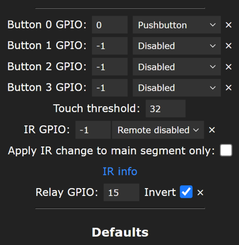
Not seeing any change / hearing your relay click? That’s because to actually have WLED acknowledge the change of the relay GPIO, we have to turn the LEDs off/on one time in the WLED overview (button in the upper left corner).
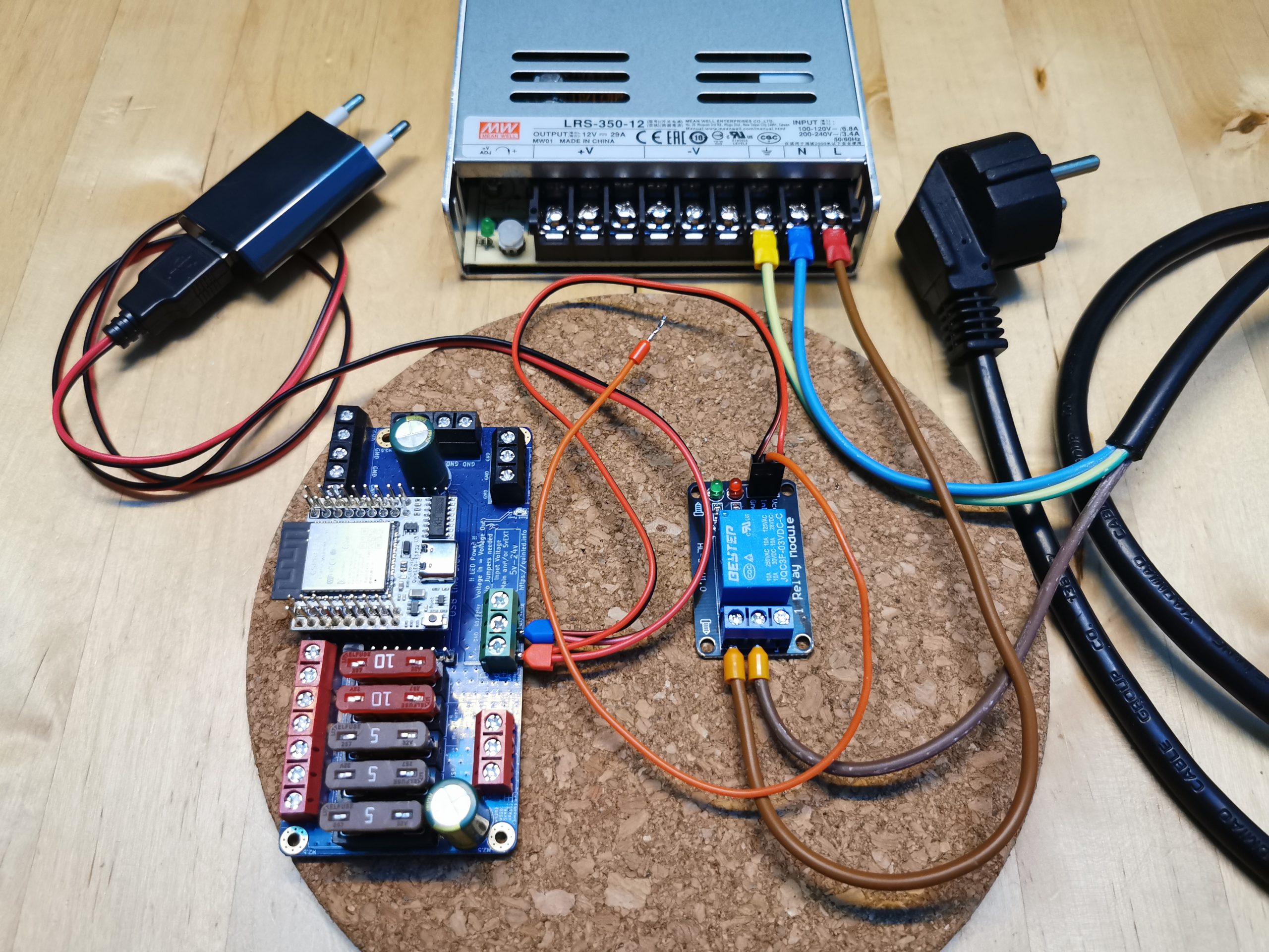
Final setup
Last step is now wiring our main PSU to the Dig-Quad, so final setup should look like this:
All done! Testing time! Ensure everything is wired correctly and plug in both PSUs. Turn off your LEDs in WLED, observe the relay clicking and you should see your big PSU having its power cut, but the Dig-Quad is still powered by the small, 2nd PSU! Turn them back on and you’ll see your big PSU getting its AC connection back and your LEDs will light up again! Congratulations, you did it!
More info on Relays
Quindor also did this whole procedure during a live stream, catch it here: QuinLED-Dig boards and using a relay and the vEXT function
Not sure which relay to buy? Of course there’s an article about this: Relay purchasing guide
And there’s also an older article (and video!) where he talks about relays in general: Home Assistant: Simple Relays With ESPHome!