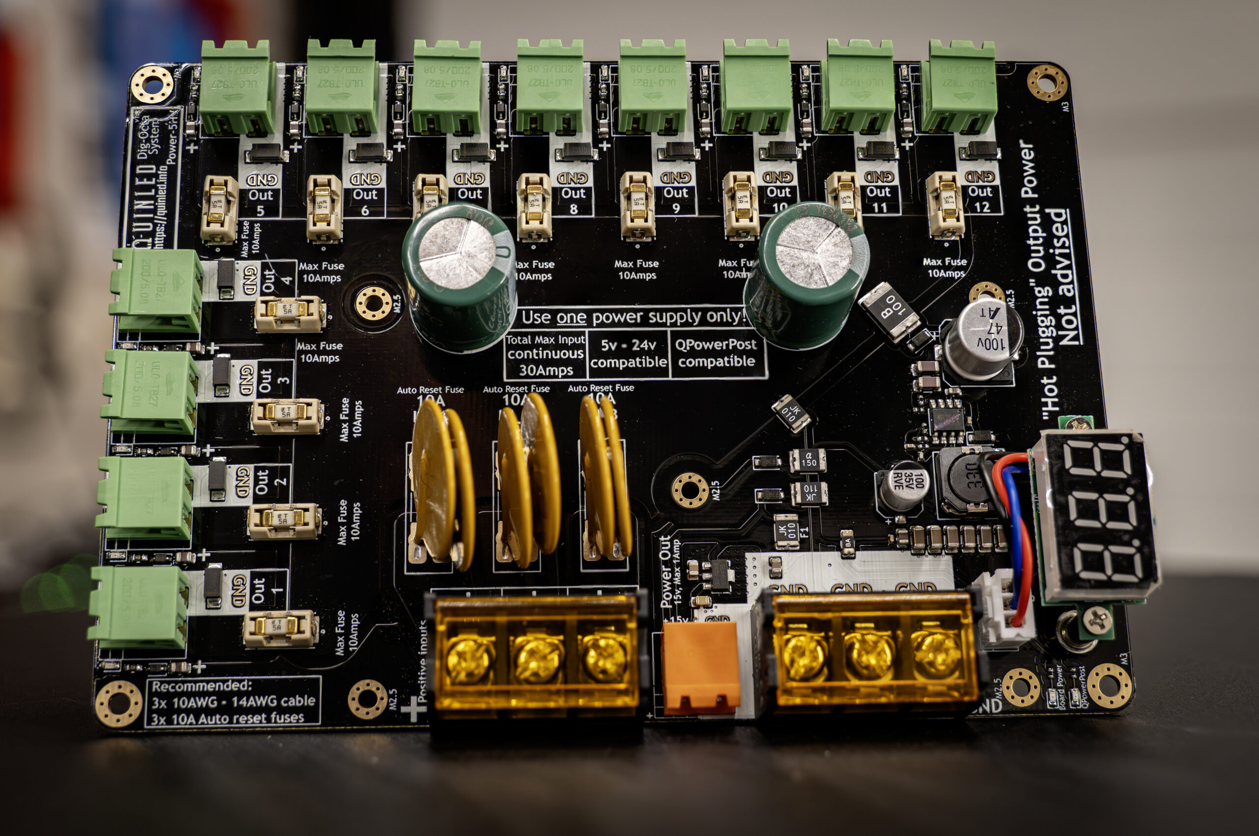
QuinLED-Dig-Octa
Power-5HV
Power Handling
When dealing with up to 30Amps of continuous power delivery there are some rules we need to follow to make sure all this power flows correctly. The below values are actual real-world tested values. There are a lot of power distribution and fusing boards out there but most are not designed to actually run their rated loads or only do so while dropping a lot of voltage which in turns results in extra heat being generated.
Especially for 48v setups it’s more important then ever that fusing is implemented and done correctly to prevent any fires or other disasters in your home, office or wherever you are using the boards.
Maximum current and fuses
- Total power continuous (24v-48v) = 30Amps
- 24v = 720w
- 48v = 1440w
- Maximum fuse for a single input terminal = 10Amps
- On this version of the powerboard this is not changeable and always 10A using auto-reset fuses!
- Maximum fuse for a single output terminal = 10Amps
- 24v = 240w
- 48v = 480w
- *Comes delivered with 12x 5A fuses since that applies to more situations
Maximum cables sizes supported
- Input 9.5mm barrier terminals
- Using fork crimp up to 10AWG/5.2mm2 is supported
- Output 5.08mm pluggable terminals
- With wire ferrule a maximum cable size of 14AWG/2mm2 is supported
Input cabling
To support up to 30Amps of power with as little voltage drop as possible the power-5HV has 3x 9.5mm barrier block input terminals which can each take up to 10AWG/5.2mm2 cable coming from the same power supply.
As noted on the board each input is rated for max 10Amps thus if you wish to use the full 30Amps capability of the board you will need to hook up all 3 input terminals (both for positive and negative).
! Using fewer input cables lowers total board current capabilities
! It is not allowed to connect multiple power supplies to a single powerboard
Suggested input cable thickness
To minimize voltage drop it’s recommended to use at least 3x 16AWG/3.3mm2 cables from the power supply finished with fork style crimps. Thicker however is recommended with 3x 12AWG/3.3mm2 probably being the sweet spot.
To learn more about sizing your power wires, please see the following article.
! Using thinner cables then suggested will cause more heat and voltage drop and could result in a dangerous situation!
Total fuses and rated continuous load
As can be seen above the board comes with 12x 5Amp output fuses bringing the total amount of current to 60Amps total but the total continuous rated power however is “only” 30Amps.
While designing your setup you need to take this into account but also please read the following:
Especially with LEDs we’re dealing with very varying or high transient power demands. At one point total power draw might be 20Amps while a few seconds later 50Amps might be drawn. As long as these are peaks and continuous load remains at or below 30Amps it’s fine to use the board like this.
*I recommend using the 50% RGB white values from my power sheets to calculate nominal load
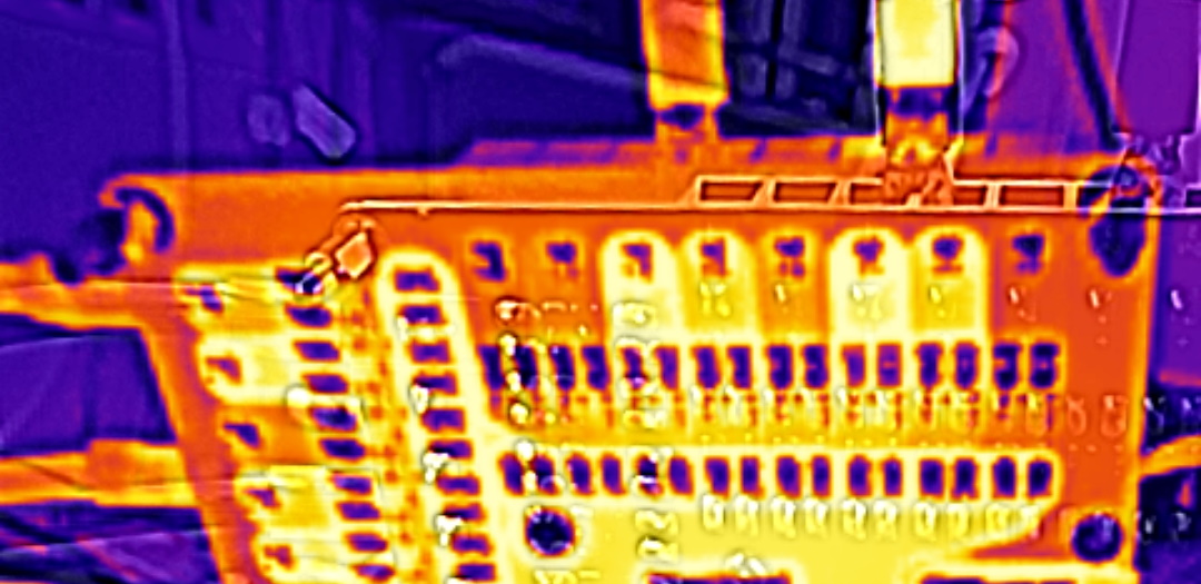
The main reason for the power rating is heat, the more current passes through the board the higher the amount of resistance and thus heat that will be generated within the copper planes and fuses on the board. The boards have been designed to only increase ~25c above ambient when running 30Amps of current through them. In a 25c room that means that the board at it’s hottest point will become 50c. So in a scenario with a widely varying load having big spikes and then lower falls in power demand is perfectly fine as long as the average doesn’t exceed the rated 30Amps.
Suggested Power Supplies
There is a dedicated article talking about suggested power supplies (with or without fan) for your 5v, 12v or 24v project. There is no article yet for 36v and 48v projects but the same brand and type recommendations apply.
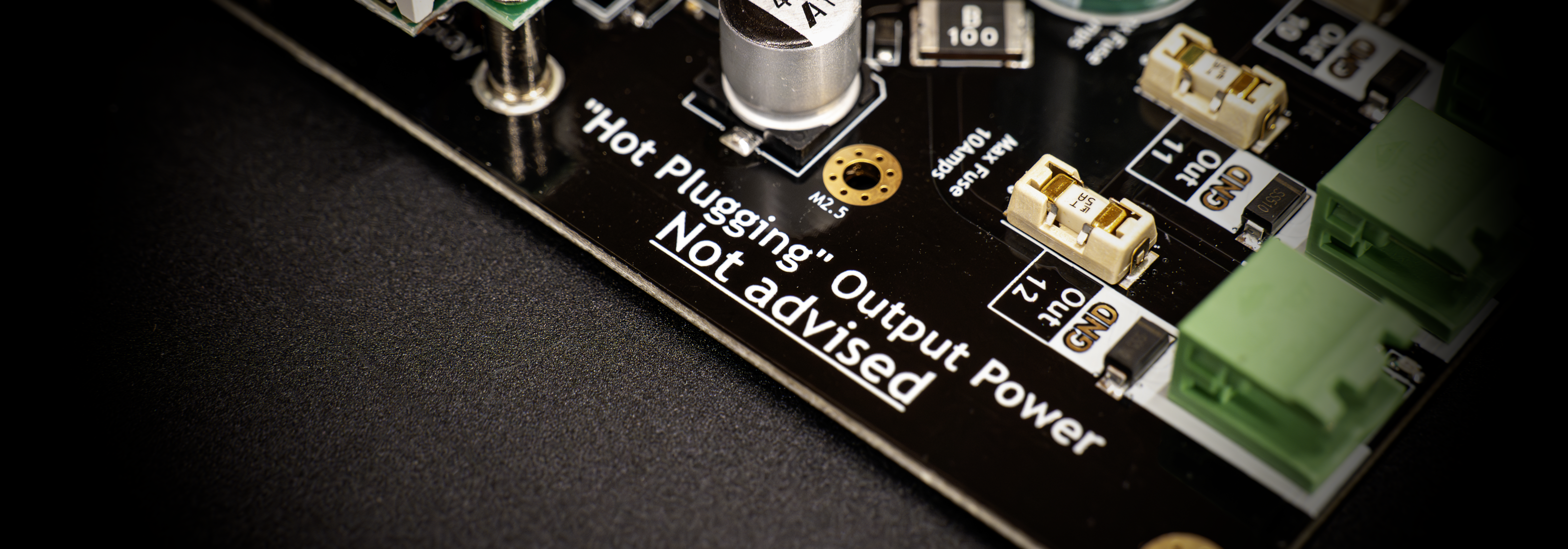
Hot plugging not advised!
Hot-plugging or the act of plugging in a power connector while power is applied was never supported but while dealing with higher voltages like 48v on the Power-5HV this has become more important. Hot-plugging an output connector into the board while there is a (large) load behind it means an enormous amount of current instantly flows often paired with a very clear “crackle” sound! While 9 out of 10 times nothing will be damaged and everything will be fine especially with 48v the amount of disturbance this causes can be much greater then say with 5v. During testing this about 50 times it was noticed that 2 times (so 1 in 25 times) the output level-shifter on the brainboard was damaged. This could have been because the LEDs I was using to test with allowed some voltage to be bridged or some other cause, whatever the case, please heed the warning, hot plugging not advised!
Spreading the heat
One thing to take into account when designing your setup is to spread out the potential heat where possible. In designing a system I often speak about edge connections and middle connections with LED strips or LED pixel strings. Roughly speaking an edge connection will draw about 4Amps maximum and a middle connection double that.
When wiring these up to your powerboard try and spread out the high current demand wires over the board with low or medium current demand cables in between. This will allow for the best usage of the power planes on the board (lowering voltage drop) and also spreading out the heat to a larger area keeping the board cooler.