QuinLED-Dig2GO Pinout Guide
A list of GPIO pins used by all components of the QuinLED-Dig2GO controlled.
For a firmware version that includes the “Audio Reactive” USERMOD please use the pre-compiled versions on https://install.quinled.info .
| GPIO | Board | Use |
|---|---|---|
| GPIO_0 | Button | Touch button |
| GPIO_5 | IR | Infra-Red Receiver |
| GPIO12 | LED Relay | LED Relay enable pin |
| GPIO16 | LED Data output | LED Data output |
| GPIO19 | Mic-SD | Microphone SD |
| GPIO_4 | MIC-WS | Microphone WS |
| GPIO18 | Mic-SCK | Microphone SCK |
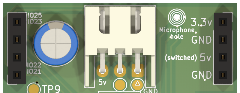
| GPIO21 | Extra GPIO | Free use (or I2C SDA) |
| GPIO22 | Extra GPIO | Free use (or I2C SCL) |
| GPIO23 | Extra GPIO | Extra |
| GPIO25 | Extra GPIO | Extra (Has ADC function) |
![]()
For the extra dupont cable connections please see the below image it will show you where which GPIO is connected and which are power. This is viewed from the top side so the same side as the button and where the dupont cable openings are.

