Dig-Octa Brainboard-32-8L “Microphone Mod”
Update: Since brainboard v2 (Selling since 2024-09) it is now possible to attach a digital microphone!
Using a v2 brainboard
If you have a v2r1 or newer version of the brainboard it’s now possible to use a digital microphone with the board.
To do so please follow the following steps:
- Get a commonly used Digital Microphone such as the INMP441
- Might require soldering of the pins!
- Disconnect jumper near the SDcard slot
- Hook up dupont wires to microphone using the new pin headers, use the following configuration:
- GND to GND
- VCC to 3v3
- SD to GPIO14
- WS to GPIO15
- SCK to GPIO16
- Make sure the build of WLED you are running has the Audio Reactive usermod installed. If you are using a build from https://install.quinled.info this should be the case!
- Activate the usermod and fill in the configuration details as shown below.


Before v2 brainboard
Some people have asked if they can hook up a microphone to the Dig-Octa Brainboard-32-8L. With the current versions of the boards this is not possible by default since literally *all* of the GPIO pins of the ESP32 are used.
The board by itself already has 2 button inputs and I2C exposed on terminals, but if you need more GPIO pins for other purposes (all pins have HW pull-up/down attached, etc.) you can free up some with a little bodge work (at your own risk, voids warranty!)!
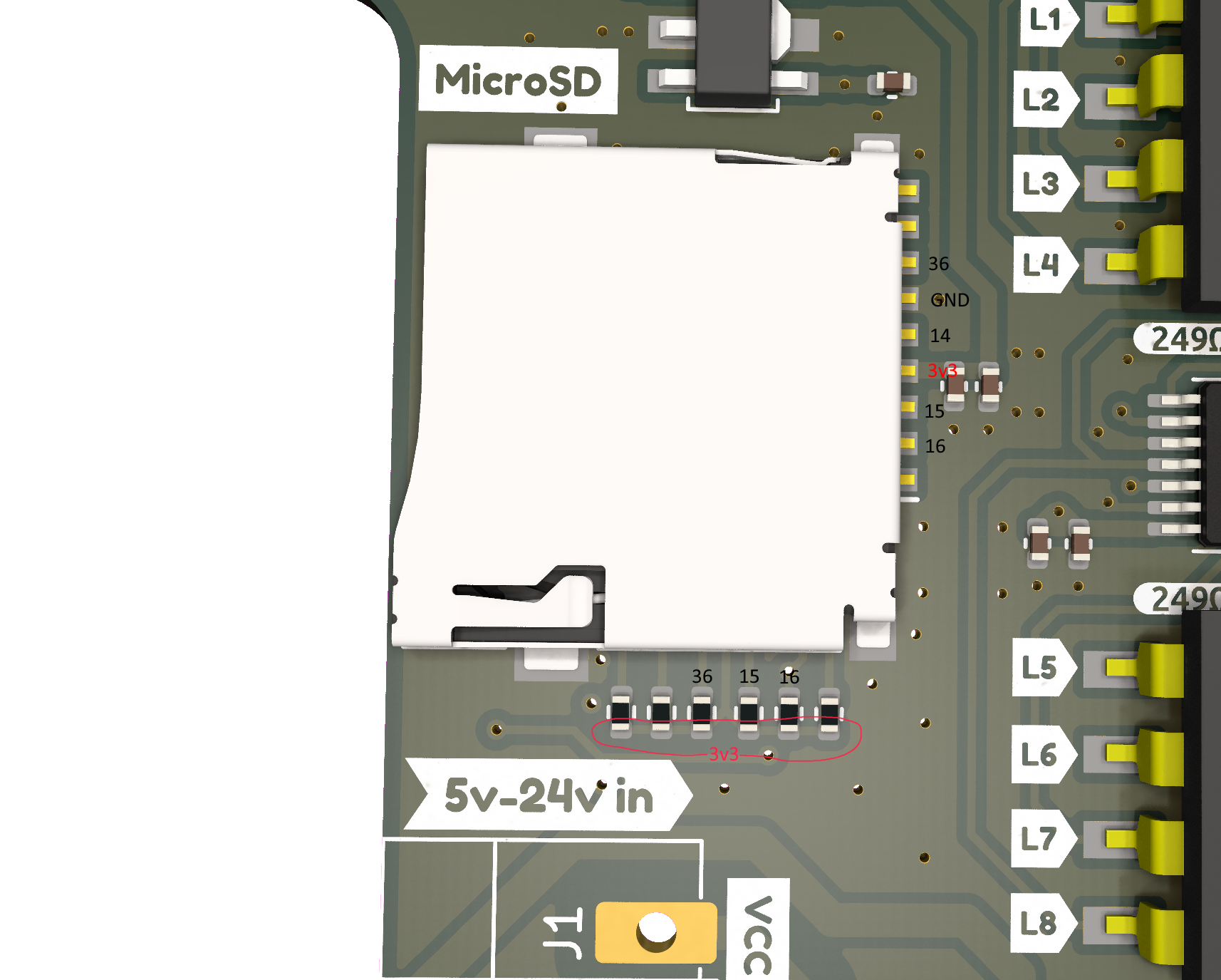
Option 1: Borrow pins from the MicroSD-card slot
The MicroSD-card on the board has 4x GPIO lines connected to it:
- GPIO14
- GPIO15
- GPIO16
- GPI36 (no output)
These can be “borrowed” from the MicroSD-card slot if you are not going to use that function. This will give you a few GPIO lines to play with to hook up other devices such as Analog or Digital Microphones.
To be able to use these lines and have fairly easy pads to solder onto the following can be done:
- Remove SDcard slot with hot air
- Maybe melt some low-melt solder into the joints first since everything is soldered with high-temp leadfree solder paste!
- Remove Resistors tied to GPIO lines with hot air or iron
Once that is done, the pads of the MicroSD-card slot can be re-used for your own purposes and double as a fairly easy location to solder your wires! Please see the following picture for where the connections are:
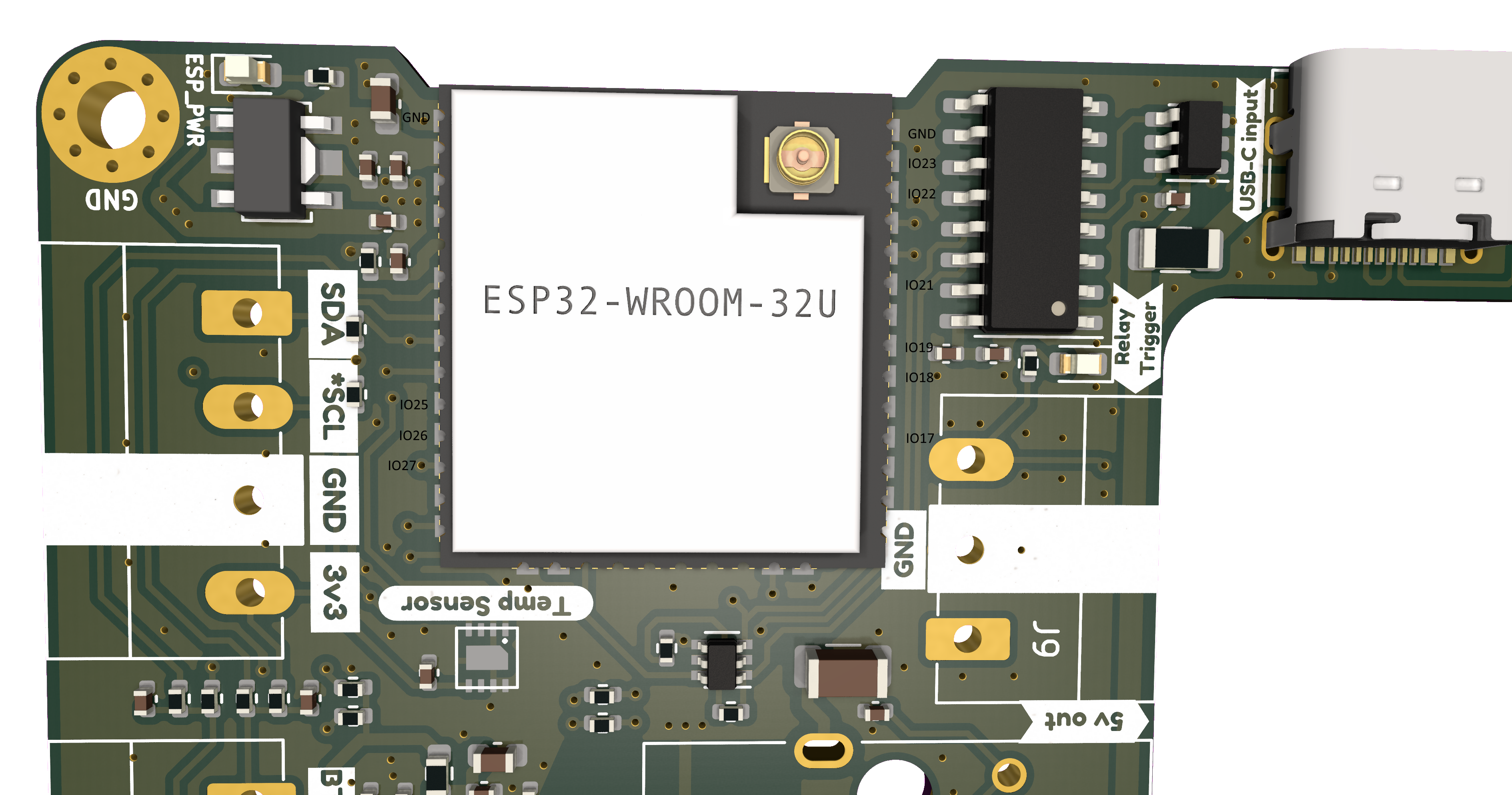
Option 2: Borrow pins from the Ethernet function
Another option, if you want to keep MicroSD-card functionality is bodging wires directly to the ESP32-WROOM module on the board. As mentioned above, all pins are used though but what you can do is turn off the Ethernet function (remove the jumper on the board) and that fully disables Ethernet and all related hardware components, including pull-up or down resistors!
GPIOs used by Ethernet are:
- GPIO17
- GPIO18
- GPIO19
- GPIO21
- GPIO22
- GPIO23
- GPIO25
- GPIO26
- GPIO27
Then you can solder wires directly to the ESP32-WROOM module (fairly easy with the castellated edges!) and use them for your own purposes! Again, be warned, this is very much for your own risk and voids any warranty! Please see the image below for the location of each of the GPIOs!