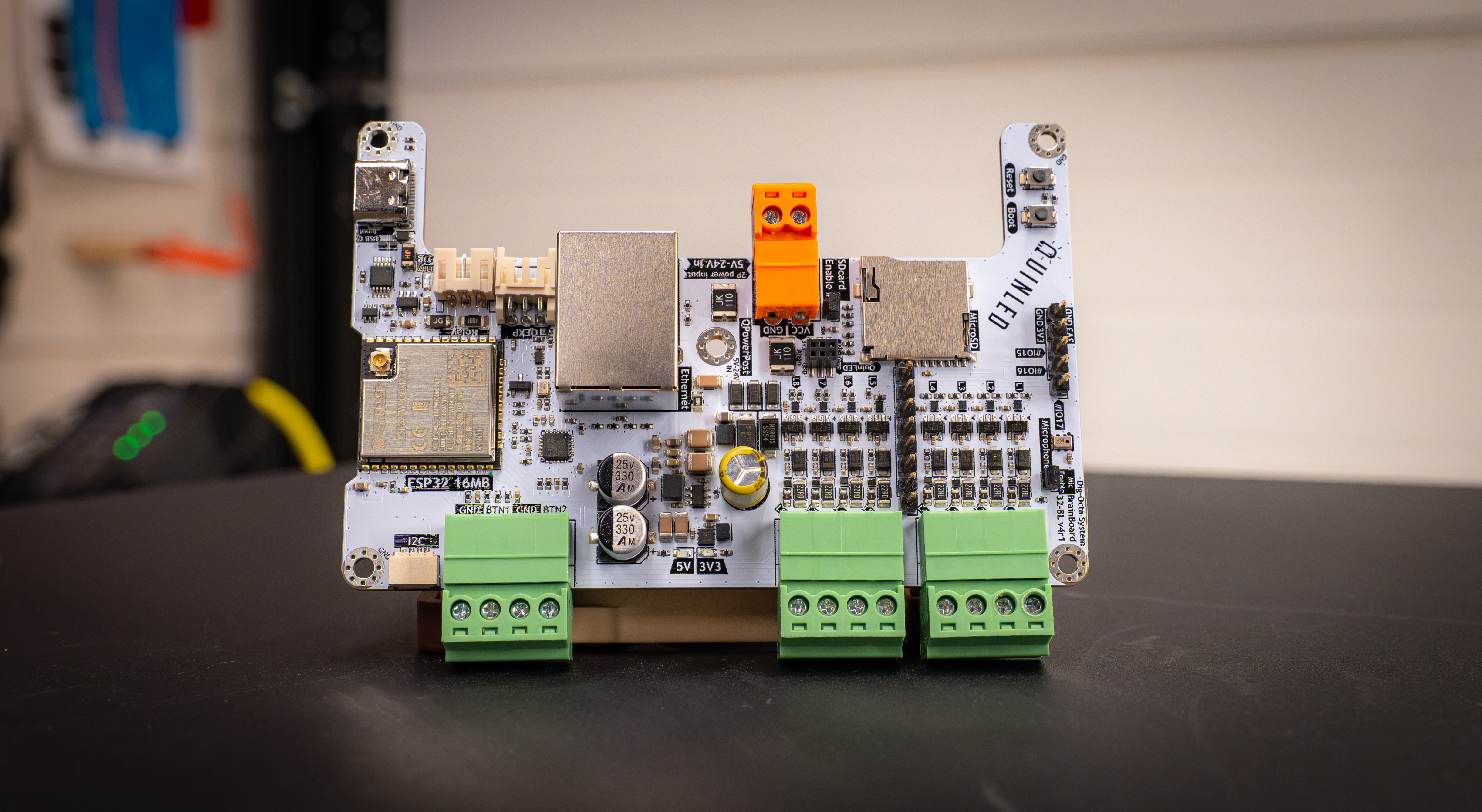
QuinLED Dig-Octa System
Brainboard-32-8L v4
Pinout Guide
The brainboard-32-8L v4 is based on the Espressif ESP32 micro-controller (see full specifications here). This makes it compatible with various software out there such as WLED or ESPixelstick or if you wish you can run your own code to run on the board.
We recommend installing firmware from https://install.quinled.info which has a lot of the below pins pre-configured for the board!
To configure it all you’ll need to know what is logically connected to the physical ports. Please see the below table for this information:
| Board | GPIO_ESP32 | Use | Notes |
|---|---|---|---|
| LED1 | GPIO_1 | LED1 Data output channel | |
| LED2 | GPIO_2 | LED2 Data output channel | |
| LED3 | GPIO_3 | LED3 Data output channel | |
| LED4 | GPIO_4 | LED4 Data output channel | |
| LED5 | GPIO_5 | LED5 Data output channel | |
| LED6 | GPIO12 | LED6 Data output channel | |
| LED7 | GPIO13 | LED7 Data output channel | |
| LED8 | GPIO14 | LED8 Data output channel | |
| Micro-SDcard | GPIO15 | SDcard - CLK | *Shared with QEXP |
| Micro-SDcard | GPIO16 | SDcard - MOSI | *Shared with I2C & QEXP |
| Micro-SDcard | GPIO17 | SDcard - CS | *Shared with I2C & QEXP |
| Micro-SDcard | GPIO36 | SDcard - MISO | *Shared with QEXP |
| I2S PDM MIC - SD | GPIO17 | I2S PDM Microphone - SD | *Shared with SDcard |
| I2S PDM MIC - WS | GPIO38 | I2S PDM Microphone - WS | |
| I2C | GPIO32 | I2C - SDA | |
| I2C | GPIO16 | I2C - SCL | *Shared with SDcard |
| Relay | GPIO33 | Relay Trigger | |
| Button input | GPIO34 | Connecting button/switch | |
| Button input | GPIO35 | Connecting button/switch | |
| QEXP - Yellow | GPIO36 | QEXP | |
| QEXP - Green | GPIO17 | QEXP | |
| QEXP - Blue | GPIO16 | QEXP | |
| QEXP - White | GPIO15 | QEXP | |
| Ethernet | GPIO_0 | Ethernet - Clock In | |
| Ethernet | GPIO18 | Ethernet - MDIO | |
| Ethernet | GPIO19 | Ethernet - TXD0 | |
| Ethernet | GPIO21 | Ethernet - TXEN | |
| Ethernet | GPIO22 | Ethernet - TXD1 | |
| Ethernet | GPIO23 | Ethernet - MDC | |
| Ethernet | GPIO25 | Ethernet - RXD0 | |
| Ethernet | GPIO26 | Ethernet - RXD1 | |
| Ethernet | GPIO27 | Ethernet - CRS_DV |
Here are the pinout for the Relay and QEXT cable, these cables are included with the controller!
-
Relay Cable (3pin PH to wire) (Cable included)
- Red = (always) 5V
- Black = GND
- Yellow = (always) 5V trigger
-
QEXT Cable (2×3 pin PHD to female dupont) (Cable included)
- Red = (always) 3V3
- Black = GND
- Yellow = GPIO36
- Green = GPIO17
- Blue = GPIO16
- White = GPIO15