
Data Signal Cable Conditioning
2023 update
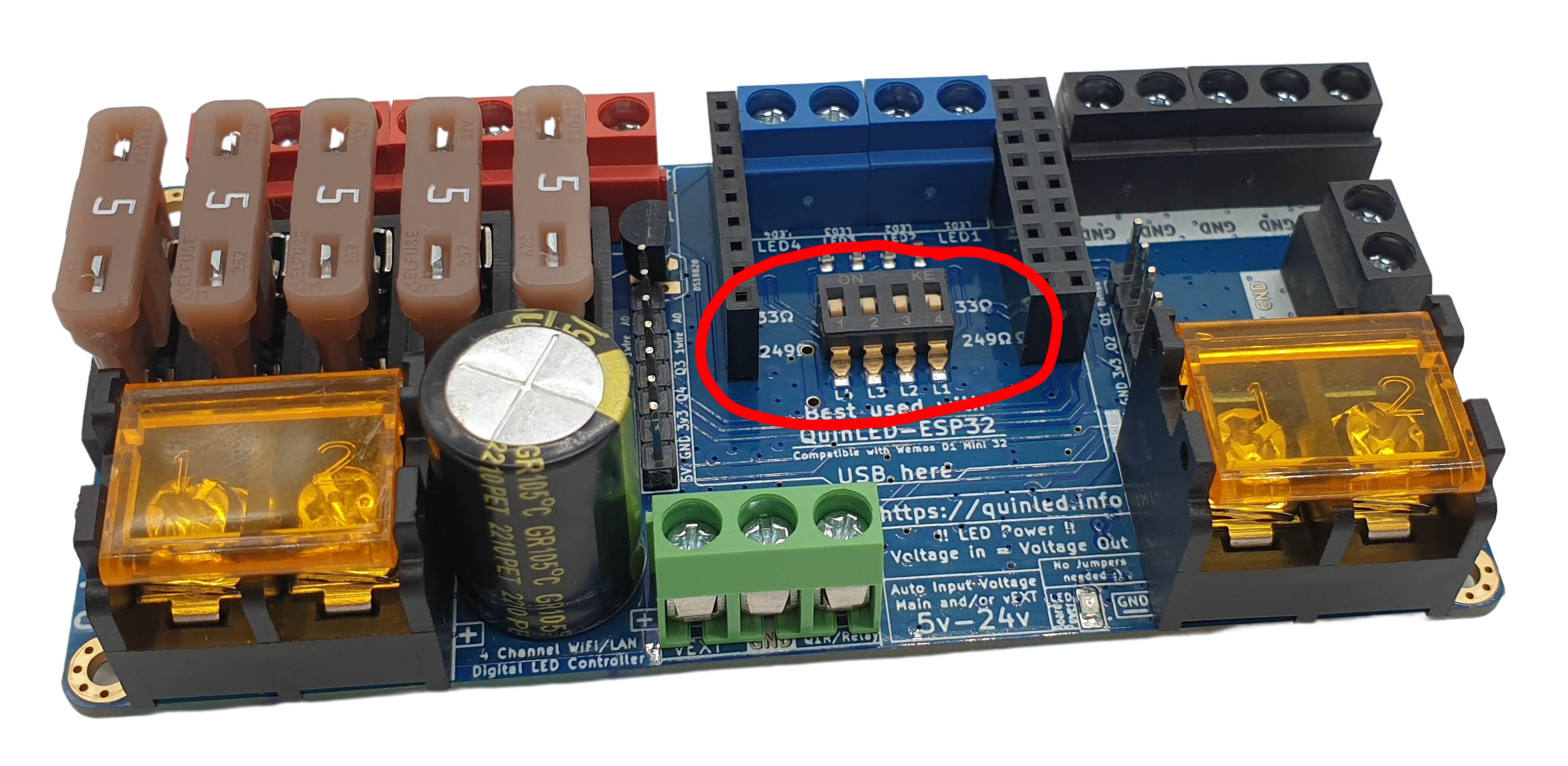
Since v3.1 of the pre-assembled Dig-Uno and Dig-Quad they have a selectable resistor switcher circuit built-in (33R and 249R) so a data-booster right behind the Dig board is not needed anymore. The Dig-Octa System also had this functionality included right from the start!
The data-booster boards are still useful for it’s other functions such as trying to connect data over (very) long distances, bridging gaps between LEDs, power injection, etc.
What is the problem?
The distance your data signal can travel has always been a much discussed subject in the Addressable LED community. The type of signal (single-ended) used isn’t particularly good at making it long distances it’s basically not engineered for that. If you really need to traverse long distances it’s best to use a differential signaling like is used in Ethernet network (CAT5, etc.) cables for instance, but without conversion the typical LED control signal isn’t suited for that.
With that said, 10m/32ft to 15m/48ft can most often be made to work. If you really need to go beyond that, differential signaling is a much better choice, I currently do not have boards for this available and this is also not what the QuinLED-Data-Booster does. I might do more about differential signaling in the future.
What we’re not diving into in this article
Officially there are things like cable capacitance effects, transmission line effects and cable resistance matching which are causes for things that are happening that the QuinLED-Data-Booster board can help you solve in your LED setup. But the technical stuff behind it is quite a lot to digest, I’m not sure I 100% understand it fully myself, so I think it’s better to just go to what happens and how it helps fix it!
Video version
I made a video version about the same subject, give it a watch!
The Myth of the Data Signal Resistor
If you read on the Internet how to hook up LED strips/pixels there are a 1000 ways described out there and generally they’ll all say some of the same but each with their own variant and twists, generally speaking they are all right and wrong, but how can that be? What is the *correct* way?!
The focus of this article (and in part the QuinLED-Data-Booster) is the data signal going to the LEDs and making it as perfect as possible to reach it’s intended target which is from the controller to the LED strip/pixel.
Where Adafruit in their NeoPixel guide advises you to use a ~400Ω resistor, others will tell you you need 100Ω or 33Ω or better yet, none! And of course, it’s all worked for them…. Now while I don’t doubt their results, there are underlying reasons and most people are not aware of where these differences come from, or what it really does.
Let’s take a look at a few scenarios:
In all scenarios I assume a setup like on the QuinLED-Dig boards with a properly implemented level-shifter, etc.!
Short length Distance, anything will work
If you are only running your data signal a short distance (50cm) and you are using a separate data wire or a 3-wire cable (data and GND close together, more about this later) basically anything you do will work fine. So from no resistor up to 500Ω, it’ll be perfectly fine and it’ll work great!
Longer distances, problems start to occur!
But moving beyond this “bench setup” length to cables that are 5m in length for instance, suddenly results are quite different. Various combinations no longer work and produce glitching, flickering or even complete LED signal corruption! But other combinations do work fine, what’s going on?!
What is going on?
Without diving into all combinations possible out there we are going to focus on 2 variants:
- Separate wires
- Single data wire + Power wires
- Bundled wires
- 2-wire or 3-wire cable
- GND is in the same cable right next to the data signal for longer distances
- 2-wire or 3-wire cable
As it turns out, the type of cable you are using has a huge influence on the data signal in your cable! Running GND close to the data signal wire causes an effect called “Transmission Line” which influences the data signal and effects it over distance. In our case, in laymen’s terms, the GND cable next to the data cable nibbles at the energy of the data signal over time, degrading it until it’s not usable anymore by the LEDS.
This effect is visible on an Oscilloscope, take a look at these examples:
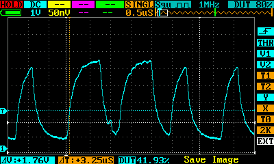
 Separate cables, 249Ω resistor, at data port
 Separate cables, 249Ω resistor, after 10m of 18AWG wire
Here you can see why I chose to use 249R on my controllers. Both the data signal output at the terminal and over 10m of 18AWG wire looks good, fairly clear edges and a clean signal.
But once you introduce a GND signal on the cable next to it, the GND basically nibbles away at the peak building capability of the data signal. Once you exceed a certain threshold (in our case cable length) the data signal won’t work anymore.
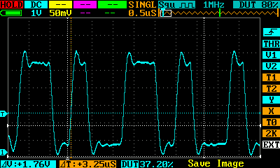
 GND + Data in same cable, 249Ω resistor, after 10m of 18AWG wire
The “fix”!
Resistor cable matching
In practice it basically comes down to matching the output resistor on your data line to the “type” of cable you are going to use. All QuinLED-Dig boards are optimized for running a separate data line. So you have you power +/- wires and a separate data wire that goes with it. Even if this runs in the same conduit or zipped together at some points, this still counts as a separate line.
The other type that is used often is 3-wire cable where you have a wire for 5v/12v +, -/GND and data close together running in the same mantle. A lot of Christmas light shows use xConnect cables and such for instance and this is a good example of such cable. It’s this type that is mainly affected by the transmission line effect and works less well with the 249Ω resistor that is on the QuinLED-Dig-Uno and QuinLED-Dig-Quad. With a data cable with GND close, up to about 3m/10ft this still works fine but longer becomes problematic.
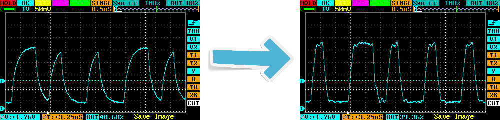
As we where able to see above, the 249Ω signal is heavily affected after 10m with ground close to it. However when we replace that 249Ω resistor with a 33Ω version the data signal gets a really big bump at the beginning over it’s waveform and this basically “resolves” the issue of having GND close to it. On the scope it looks horrible at the data port (not shown), but in reality it does allow the 3-wire variant to go 10m or 15m in distance so it’s an effective “fix”!
These measurements where taken behind a QuinLED-Data-Booster(-Maxi) board connected to a QuinLED-Dig-Quad!
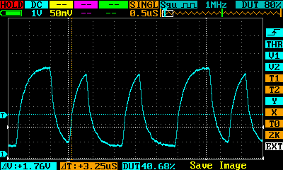 GND + Data in same cable, 249Ω resistor, after 10m of 18AWG wire
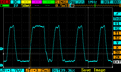
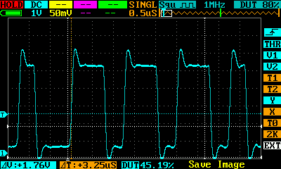 GND + Data in same cable, 33Ω resistor, after 10m of 18AWG wire
As you can see sending out the data signal through the 33Ω Resistor makes a huge difference to how it arrives at the LEDs when GND is present right next to the data signal wire and this again works great, no more flickering or corruption on the LEDs!
No single “right” value
And that’s partially the cause of introducing the QuinLED-Data-Booster(-Maxi) board. When placed directly behind a QuinLED-Dig-Uno or QuinLED-Dig-Quad it allows you to change the data signal conditioning for a channel to match to the cable you have behind it!
Another way would be to de-solder the 0603 249R 1% resistor on the QuinLED-Dig boards and solder a new 0603 33R 1% in it’s place, this has the exact same effect! Please see here for the Dig-Uno and here for the Dig-Quad. But since not everyone is comfortable doing so the QuinLED-Data-Booster(-Maxi) is an easy alternative for that.
Why not just use 33Ω?
If the data signal works with the 33Ω resistor, why not just use that? The main reason is that I wanted to optimize my controllers for a use case and in this case that’s running the separate data wires and getting a good clean signal out of the board. I did a lot of testing with that and then chose the 249Ω value. Later it turned out this worked less well with the 3-wire cables, but in my opinion, my results and readings are still correct for the “designed for” scenario, so the controllers won’t change. But like I started saying at the beginning of this article, all our setups are different and so I want this information to be out there so you can adapt your setup to the ideal values yourself! So I decided to develop the QuinLED-Data-Booster(-Maxi) board instead, giving everyone an easy solderless solution if they run into this problem on some of their LED runs!
Regarding no ideal value resistor, in testing I saw the following:
- 10m separate data wire works great with 249Ω but shows corruption with 33Ω
- 10m 3-wire cable works great with 33Ω but shows corruption with 249Ω
So there is no “golden” value resistor. Yes you can select a value somewhere in the middle but then you are going to hurt both types of scenarios and reduce the length possible ultimately. As said, I’d rather optimize for one scenario and provide a solution for the other. If you can solder, replacing a single resistor per channel will do that, but if you can’t or don’t want to, the QuinLED-Data-Booster(-Maxi) is here to help you solve it that way!
More articles about these resistors and possible setups will follow in the future!