
QuinLED-Dig-Uno Wiring Guide
QuinLED-Dig-Uno board v3 has been released, please go here for pinout guide
In this guide there might be references to L1_C and L1_D, these names where changed on v3 boards to LED1 and LED2 respectively.
Wiring Guide
Wiring LED strip seems simple but becomes more complex the longer the length becomes. The QuinLED-Dig-Uno has been designed to try and make cabling easy for small to medium installations. It does this by allowing you to run a pretty high amount of current through the board instead of having to run positive and negative wires separately. If you wish to run larger wattages (15Amps+ continuous), stepping up to a QuinLED-Dig-Quad is advised!
The QuinLED-Dig-Uno board allows you to either use a ESP8266 or ESP32! Although that gives you a lot of flexibility, it does make selecting the right pins a bit harder, hopefully the pinout guide clears that up! Version 3 of the QuinLED-Dig-Uno has been heavily optimized towards running an ESP32 and making the Ethernet option available. If you wish to run the board primarily with an ESP8266, using a v2 board is advised!
The board can be built DIY with the option to enable 12v input compatibility. The pre-assembled boards of the newest generation are 5v-24v compatible, please note the marking on the board version you have! Although this doesn’t make a difference in wiring it up it can make a difference in designing your LED install. Generally speaking 12v Digital LED strip can be run in longer lengths and with more LEDs without suffering as much voltage drop as their 5v counter parts.
Make sure to also check out the following pages, QuinLED-Dig-Uno power limits. Also, make sure to check out the wire thickness needed page to determine what thickness cable you require for your desired lengths and application! Also remember to provide proper cooling for your LED strip although with Digital LED strip it is very dependent on what is going to be displayed, random color don’t generate too much heat but sustained white output will quickly burn up your LEDs!
Digital DATA Signal
Different then with analog LED strips, digital LED strips have a voltage +, – but also a data signal or even a clock and data signal wire. The thing to remember about these is that while power can travel both ways, the data (and clock) signals need to follow the arrows on the strip and thus are one directional. You don’t have to worry about data or clock signals degrading because they are boosted by each LED package. So just make sure when soldering on your wires or applying the strip in it’s final destination, check that the arrow is pointing in the right direction!
Length/Density/Power configurations
If you are running a low to medium power configuration (sustained up to 15A or 75w at 5v and 180w using 12v) you can run all the power through the board. Make sure the cables connected to the LED strip are thick enough to transport this amount of current. The generic tiny wires soldered to the strip can be ok for short distances but if you are going to use it seriously it is advisable to replace them by soldering thicker wires to the LED stip.
Another concern is voltage drop, although the board might be able to handle it, especially with 5v Digital LED strip voltage drop over the length of the LED strip is a real concern. This will often still require “injecting” power along the strip or at the end. But this depends on how many LEDs the strip has, a 5m strip with 30LEDs/m can be fine but a 2m 144LEDs/m will need power injected in the middle or on both ends for sure. So in the case of digital LED strip the amount of LEDs and their density is more important than the actual length of the strip.
Also power draw depends on a lot on the patterns displayed on the strip. If there is a lot of white for instance power usage will be very high but for random star patterns and such in color power draw will be a lot lower. The below scenarios take into account being able to use your LED strips for not so much worst case scenarios (that’s 50w per meter which is 10A!) but I guess you could call it medium scenarios. Not very light, but not totally fully loaded either. So they are guidelines which work well in practice, please take note of them, running too much power through too tiny wires can create a fire.
With that said, please take a look at the following diagrams:
5v
5v, ws2812b, short length/low density
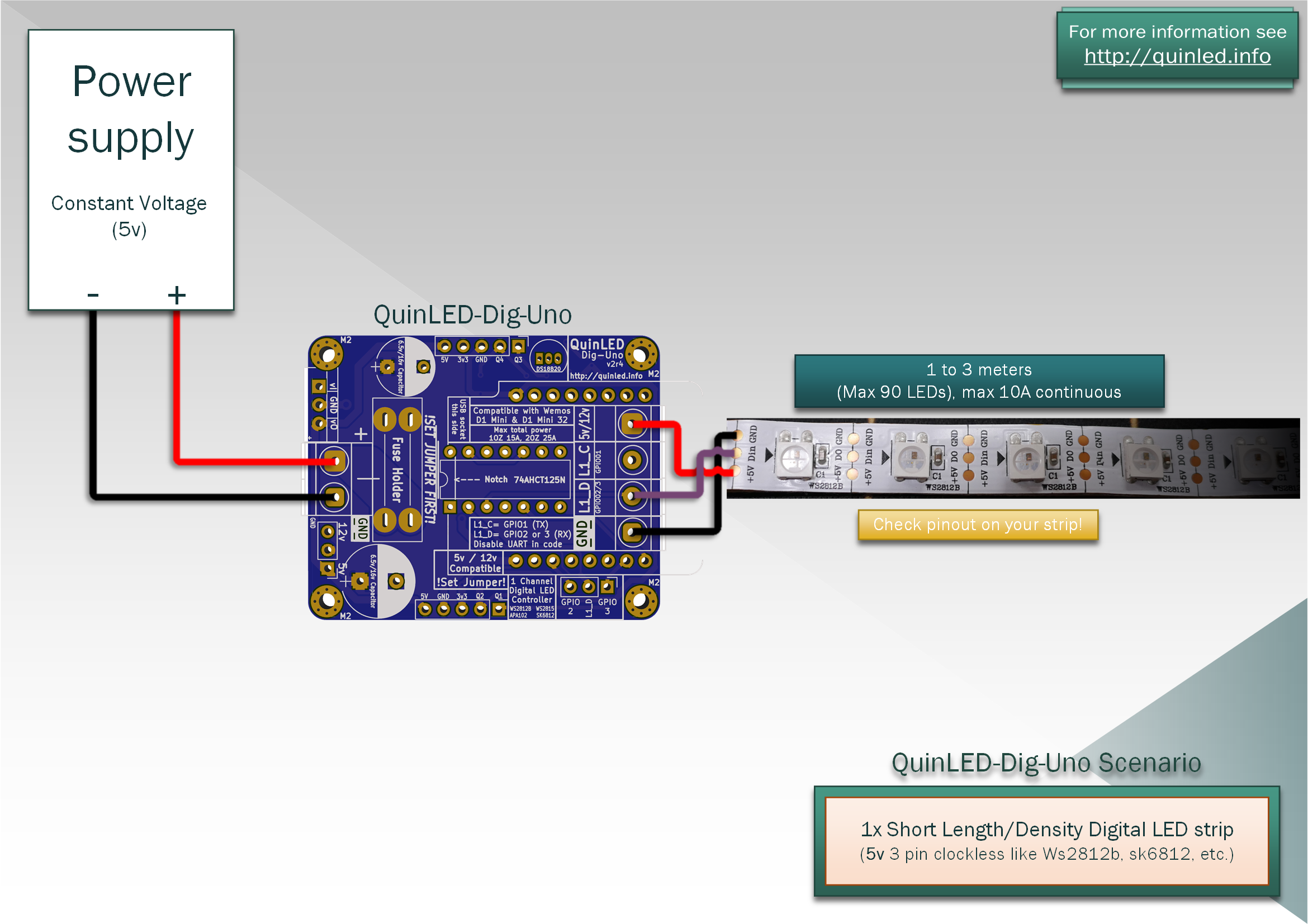
This configuration is using low density 30 LEDs/m strip and max about 3 meters of strip. Or using 60 LEDs/m but about 1.5 meters. If you don’t exceed 90 LEDs you will probably be fine feeding the strip from one side only as depicted.
5v, ws2812b, medium length/density

For a longer strip and/or more LEDs you need to supply power (+ and -) on both sides of the strip. This way you can go up to 5v meters on low density 30LEDs/m strip but if you are using 60LEDs/m I would suggest looking below because a 5v strip has too much voltage drop to stay consistent even while feeding both sides.
5v, ws2812b, high length/density
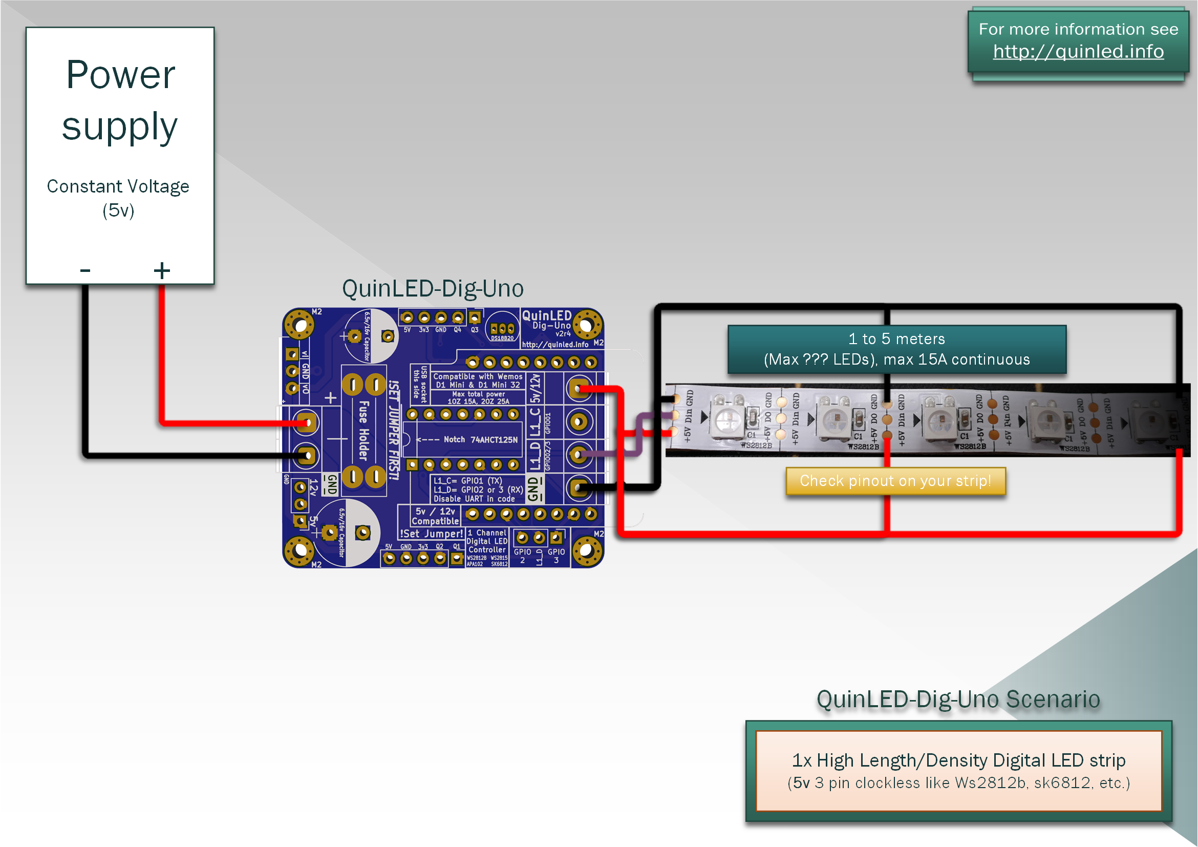
If you are using longer 60LEDs/m strip you will need to inject power at the beginning, middle and end of a 5m or 300LEDs strip. If your strip is longer or a higher density you will need more power injection points. For 144LEDs/m strip at 5v I recommend injecting power every meter!
5v, APA102, low length/density
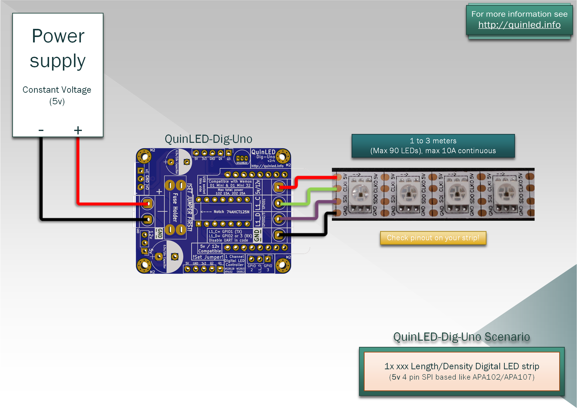
Instead of 3 wire LED strip this is a 4 wire SPI LED strip. In regards to power handling and hooking it up they are exactly the same as the previous examples they just have an extra signal wire next to the data wire to connect.
12v
(Newer pre-assembled boards have no more jumper and are “auto-voltage”!)
Set Red Power Jumper to 12v position before connecting power!
12v LED strip wiring it basically more of the same as above but you can get away with less wiring for more LEDs. Here is an example of that:
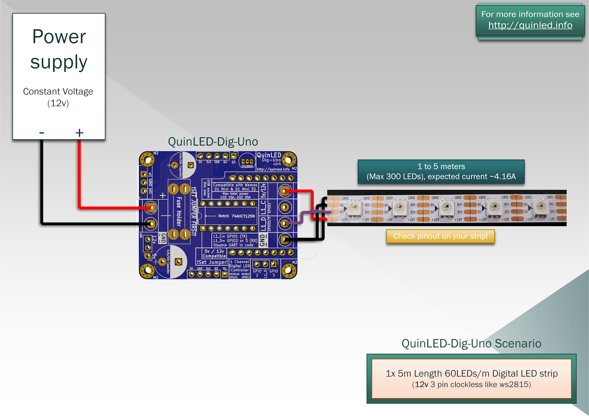
Because of the 12v power you can now power up to 300 LEDs with only feeding the beginning of the strip. If you where using 5v you would have at least needed to inject power in the middle or even at front + middle + end to achieve full power output. This diagram also shows how to hook up the primary and backup data signal. Next to running a wire to GND you can also put a solder blob at the beginning of the strip connecting it to GND that way. The first LED will then generate the backup signal.
Bonus configuration
Although the QuinLED-Dig-Uno name clearly infers that it’s a single channel controller, using the ESP32 it’s actually possible to use 2 clockless (WS2812B, WS2815, sk6812, etc.) LED strips with this board! Both the LED1 and LED2 are run through the level shifter independently, so there is no downsides to doing this! Make sure not to exceed total board power limits though.