Why Ethernet cable (CAT5e, CAT6, etc.) isn’t suitable for LEDs
Often people ask if they can use some left over CAT5e or CAT6 Ethernet cable for the LED installations for providing data and/or power injections to their LEDs. The TL;DR of the story is that Ethernet cable isn’t very suited to running LEDs and it’s best to use normal 2-wire/3-wire type cable, I have more details about doing so here but if you want to know the technical background behind this, read on!
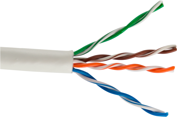
Further in this article “Ethernet cable” will be referred to as UTP since that’s basically what it is, UTP stands for Unshielded Twisted Pair. Any form of STP, SFTP or other variants don’t really make too much of a difference (or I’ll note it!).
In regards to Data signaling

Type of signaling for digital LEDs
The type of signals our ws2812b, sk6812,ws2811 or any other type of LED uses is called a “singled ended” signal. This means 1 data wire that carries the signal and it’s 1’s and 0’s are basically linked to GND.
Ethernet cable with it’s “UTP” (Unshielded Twisted Pair) structure was invented for a different kind of signaling called “differential signaling“. This uses 2 wires and basically each wire is a reversed mirror of each other. So for a 1 you’d have +3.3v and -3.3v on the pair of cables. This makes the signaling much more robust and also a lot more immune vs outside noise.
Single ended signals are usually used for short distance and relatively low speed signals. Differential signaling is used for signals that need to travel longer distances or need higher speeds. For instance your home network with it’s 100Mbit or 1000Mbit (or more) networking uses this type of cabling, other standards such as RS485, etc. also use a similar 2-wire differential signaling approach.
–2024 update
I have introduced the QuinLED-Diff series of boards which take in the single-ended data signal, convert it to differential (RS-485) and then back again at the receiving end. With this solution it’s no problem sending LED data signals up to 500m/1600ft!
Is differential signaling the same as data+clock LED strip?
No, data + clock LED strip such as APA102 and clones use 2 distinct signals, not a reversed mirror of one signal like with a differential pair signal.
Can I run an LED signal through a UTP wire?
Yes, you most certainly can but the question is if you should! If you take one of the 8 wires from the UTP cable you can run a signal through there like any other wire! But if your question then becomes, can I run multiple digital LED data signals through a single UTP cable the answer is a no or rather, you shouldn’t. Because of the type of signal (see above) having multiple of these signals very close or worse, twisted together even, they are going to have a bad influence on each other and this will cause corruption into the data signal very quickly! “But it works for me for my 1m cable” yes, that’s a short length and thrown together with a bit of luck it might work for you, still doesn’t mean this is a good solution.
When running a single signal through an Ethernet cable a 50Ω resistor is advised. The QuinLED-Dig boards allow you to switch between 249Ω (Default) and 33Ω. Since it’s advised to run a GND wire next to the signal wire in these types of cases the 33Ω (to the 50Ω impedance of the Ethernet cable) comes closest and will provide the longest distance for that data signal.
So data signal, sure, you can run 1 data signal through the cable, but more then that is not recommended.
Aren’t twisted wire pairs better?
Yes, for differential signals. It does nothing for single ended signals, at all. See heading “Type of signaling for digital LEDs” above!
CAT7 / PIMF cable
One exception to the above rule might be CAT7 or rather PIMF cable. PIMF stands for Pair in Metal Foil and this type of cable basically encases each wire pair in it’s own foil, next to having a metal braid around the cable as a whole. If you make sure the pair (so both wires) runs the single ended data signal and the foil is GND, having multiple of those types of signals in that same cable, basically shielded from each other by GND might work. So maybe, in theory it could be used to transport a max of 4 LED data signals, but this is completely untested and unverified!
In regards to Data signaling – Conclusion
If Ethernet cable is the only cable you have lying around and aren’t going to use it for anything else it can be used to transported 1 single-ended LED data signal to digital LEDs!
In regards to power
A lot of folks seem to want to use CAT5e or CAT6 for power, just because they are used to using this type of cable and feel like it already exists and is widely used with POE (Power Over Ethernet).
Calculation scenario and rules
For all calculations we’re going to assume the below scenarios. These are based on common LED installation requirements and doing power injection to a front and middle point. To learn more about these values, see the tests here.
5v scenarios:
1m – 4Amps
6m – 8Amps
12v scenarios:
1m – 4Amps
6m – 8Amps
Bonus 24v:
10m – 5Amps
As with any digital LED power injection the rule is that the injection cable should not drop more then 10% voltage to be suitable.
For all calculations the following online voltage drop calculator was used.
This article assumes actual copper cables
Any and all cables in this article we are talking about cables actually made from copper. If you browse Amazon a lot of cables that are offered (especially Ethernet) are known as CCA cables. These are *not* actually copper cables! CCA stands for “Copper Clad Aluminum” this means the wires are actually Aluminum and then have a very thin copper coating. The properties of Aluminum are different from copper in that it for instance has a higher resistance. So in any regard CCA cable will be even worse then the calculations below!
This article assumes solid copper cables
Ethernet cable can be bought in 2 variants, solid or stranded. Solid is meant for any installation type cable such as in wall. Standard is meant for the shorter pieces outside of the wall. So for instance in the Ethernet specifications when they mention 100m distance they really mean 10m + 80m + 10m. So 2x 10m stranded patch cables (nice and flexible, easy to plug in, etc.) and 80m of solid cable that runs through the wall for instance.
In this article we’re basically going to talk about solid core wire although in regards to electrical properties they are not that much different, solid cable has slightly better conductivity vs the same diameter stranded cable.
Current handling capacities
Looking online most UTP cable is either AWG26 or AWG24. For our calculations we’ll use the larger AWG24 diameter. Compared to regular 2-wire or 3-wire cable, these conductors are quite thin.
Dividing conductors
Power injection should always be done with Positive and Negative so this means if we have an 8 conductor cable that will purely be used for power you’d have to divide the conductors equally between 4 for positive and 4 for negative in the best case scenario. If we also want to include data I’d suggest having 3x Positive, 1x data and 4x GND or negative. Make sure that the pair that has the data signal has GND on the other wire.
One conductor vs multiple
Let’s calculate the current we can transport over 5m/16ft with a generic CAT5e UTP cable just used for power injection. If we use a single conductor, things are easy, we plug in our AWG24 value into a voltage drop calculator and let it calculate.
Single conductor
One conductor 24AWG, 1m – 5v / 4Amps: FAIL
Voltage drop in volts: 0,67v
Voltage drop in precent: 13,4%
One conductor 24AWG, 1m – 12v / 4Amps: PASS
Voltage drop in volts: 0,67v
Voltage drop in precent: 5,6%
One conductor 24AWG, 6m – 5v / 8Amps: FAIL
Voltage drop in volts: 8v
Voltage drop in precent: 161%
One conductor 24AWG, 6m – 12v / 8Amps: FAIL
Voltage drop in volts: 8v
Voltage drop in precent: 67%
One conductor 24AWG, 10m – 24v / 5Amps: FAIL
Voltage drop in volts: 8,4v
Voltage drop in precent: 35%
Well, that doesn’t look good, only the 1m – 12v / 4Amp test basically passed the below 10% drop rule! Our bonus test with 24v also can’t fix that. But let’s see what happens if we use multiple of the conductors!
Multiple conductors
To calculate the combined wire diameter of our multi-stranded cable we’re going to use the following tool. This tells us that combining our 8 conductors in 4x positive and 4x negative we go from an effective cable diameter of 24AWG to 18AWG! That’s with no data in this cable, just power! Ok, let’s do those calculations again and see if that improves things!
All conductor ~18AWG, 1m – 5v / 4Amps: PASS
Voltage drop in volts: 0,16v
Voltage drop in precent: 3,3%
All conductor ~18AWG, 1m – 12v / 4Amps: PASS
Voltage drop in volts: 0,16v
Voltage drop in precent: 1,3%
All conductor ~18AWG, 6m – 5v / 8Amps: FAIL
Voltage drop in volts: 2v
Voltage drop in precent: 40%
All conductor ~18AWG, 6m – 12v / 8Amps: FAIL
Voltage drop in volts: 2v
Voltage drop in precent: 16.7%
All conductor ~18AWG, 10m – 24v / 5Amps: PASS
Voltage drop in volts: 2v
Voltage drop in precent: 8,7%
This does look a bit better! Now our 1m front injection passes for both 5v and 12v work but alas the 6m middle injection still fails for both. The bonus scenario with 24v also gets a pass but only because now 10% drop means 2,4v!
Power Handling – Conclusion
Looking at the results you could say that Ethernet cable can be suitable to transport power. In my opinion that isn’t completely true though. All the longer results except for the bonus 24v test basically failed. For short distances such as 1m it’s likely going to work fine but as distance increases even with all cables combined (no data signal) the Ethernet cables just don’t have a lot of copper in there so they don’t make a great medium to transport power. Above calculations also assume high quality 24AWG cable which most generic cable isn’t those are more likely 26AWG which makes everything even worse.
Still, it’s equivalent to 18AWG cable if you terminate it with 4x positive and 4x negative. If that’s suitable for your application, it can be a viable alternative if you have it lying around for free and are never going to use it for anything else again. In all other cases I’d recommend just buying some decent cables that are meant to transport power.
But what about POE?
All of the above is nice, but millions upon millions of devices worldwide are powered using Ethernet cables and the POE standard! What’s up with that, why are you saying we can’t use Ethernet cable while all these various devices are powered by it?
While that is correct, there are a few fundamental differences how these devices work vs how our LEDs work, let’s dive into that a little bit.
Very high voltage
POE inherently runs at a very high voltage. The most known voltage is 48v but this is more of a nominal voltage now a days and POE switches regularly run at 52v up to 57v! If we have 1Amp of current at 12v this means we have 12watts. Now running that same 1Amp of current at 52v means we have 52w! So a high voltage helps transporting more energy over a small diameter cable.
But here-in also lies our problem.
Non-converting end device problem
A POE device basically always has a buck-converter onboard that will convert whatever voltage is coming in say between 35v and 57v to whatever voltage the device usage natively be it 12v, 5v or even 3.3v. This means the incoming voltage doesn’t have to be precisely a certain voltage since it’s going to be converted anyway and that converter doesn’t care, it can make 5v from 35v or 42v or 48v.
Our LEDs run at exactly 5v or 12v, no converting is taking place there anymore. This means that if only 4.5v is left after going through our cable, the LEDs are running 0.5v lower voltage and this will directly show as voltage drop, the exact problem we’re trying to prevent.
And well, that’s the big difference between POE or directly powering something through an Ethernet cable. Even “hacked” POE which just passively runs 12v or 24v through a cable like Ubiquiti or Mikrotik support works the same way, those devices can operate perfectly fine with say 8v coming in. So even if you put 12v on the cable and the end device receives 9v because of voltage drop over the thin Ethernet wires, this is no problem.
POE is very limited power
I have a dedicated article about using POE for powering LEDs and we did all kinds of practical investigations. The end result is that it’s possible to run LEDs over POE but that because of the limited power available it’s only suitable for a limited number of LEDs.
Here is a very useful table that shows you the actual specifications and power that can effectively be used using POE:

End conclusion
Although Ethernet cable in the end is just copper wire like any other wire, the properties that make Ethernet uniquely suited for it’s purpose don’t really help in powering LEDs or providing them with data. For that purpose it’s mismatched and often more expensive cable with no benefit above normal cable. As stated in the article, if you have loads of free Ethernet laying around it can be used in some scenarios but in most you are much better off buying the proper cable meant for the task at hand!