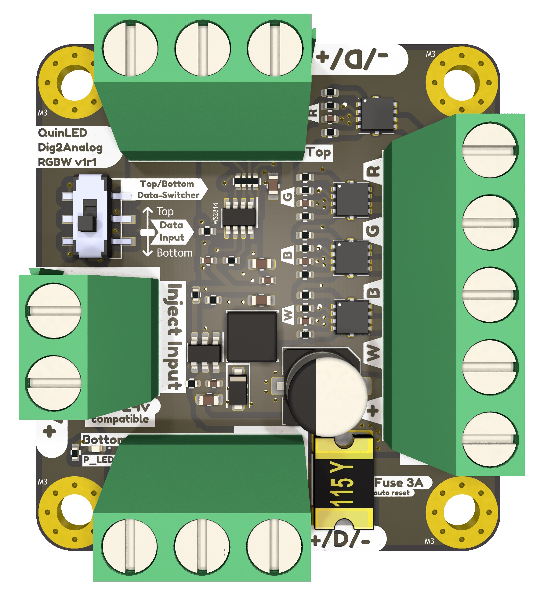
QuinLED dig2analog specifications
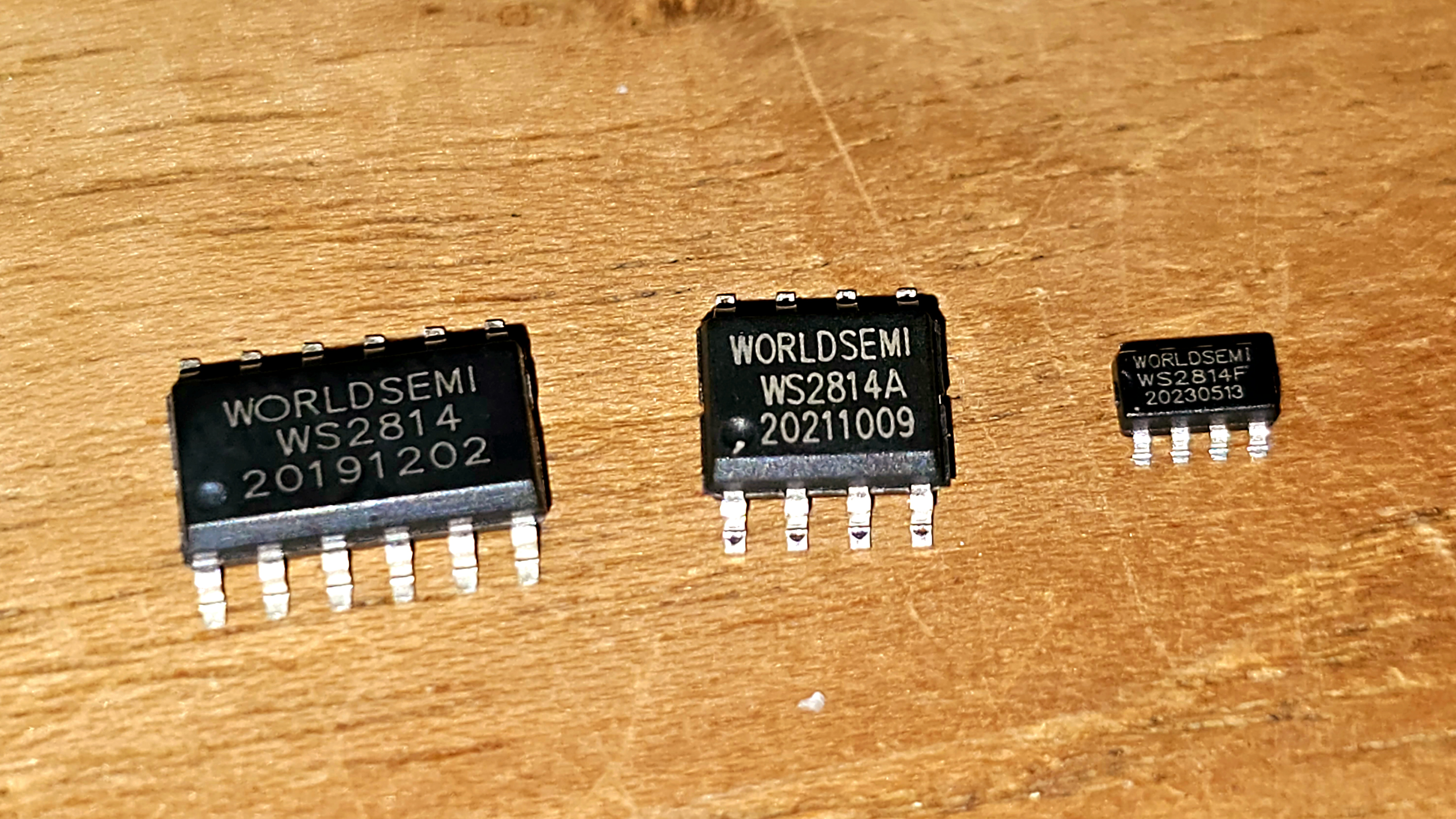
The dig2analog is based on the WorldSemi WS2814F chip. This chip is used to “extract” the data for a single LED/Pixel and the board converts it to a PWM output able to drive 12v or 24v LED strips up to RGBW.
The onboard circuitry has been carefully tuned to be both efficient and have great performance. Other similar type boards use cheap/simple circuits but the result is often sub-par in regards to high idle power usage, driving capability, board temperature or have inverted control logic.
The dig2analog uses a fully custom DC buck converter setup to eliminatie idle usage together with carefully tuned resistor values enabling both very low PWM levels as well as a correct full 100% (no PWM) output at the high end. The special “dual” MOSFETs on the board auto invert the signal in hardware so you don’t have to worry about this in software.

Features
- Uses newest WorldSemi WS2814F chip
- Up to RGBW output
- 2kHz PWM frequency
- ws28xx protocol compatible
- Coupled with 33R output resistor
- Allows up to 10m* distance between dig2analog boards
- *Depends on specific setup and possible outside interference!
- Best suited for 2-wire (Data+GND) or 3-wire (Positive+Data+GND) cable
- Allows up to 10m* distance between dig2analog boards
- 12v – 24v compatible
- Fused Output to LED strip with 3A self reset fuse
- Power Handling up to 6A (see separate power handling article for more information)
- “Link through” and separate Power injection terminals available
- Easy to daisy chain boards and feed in power into the chain where needed with extra injection wires
- Up to 15A current input/throughput with very low resistance for daisy chaining boards and power distribution
- Fused Output to LED strip with 3A self reset fuse
- Chainable up to max 400 per “data channel” recommended
- That’s 1600 analog channels!
- Uses special “dual” N-channel MOSFETs
- No reversed data signal needed in software!
- Data input side switcher
- Allows you to change data in/out between top or bottom 3p terminals allowing the dig2analog to be used whatever orientation works best for your setup
- Set the switch to the side that will receive the data
- Allows you to change data in/out between top or bottom 3p terminals allowing the dig2analog to be used whatever orientation works best for your setup
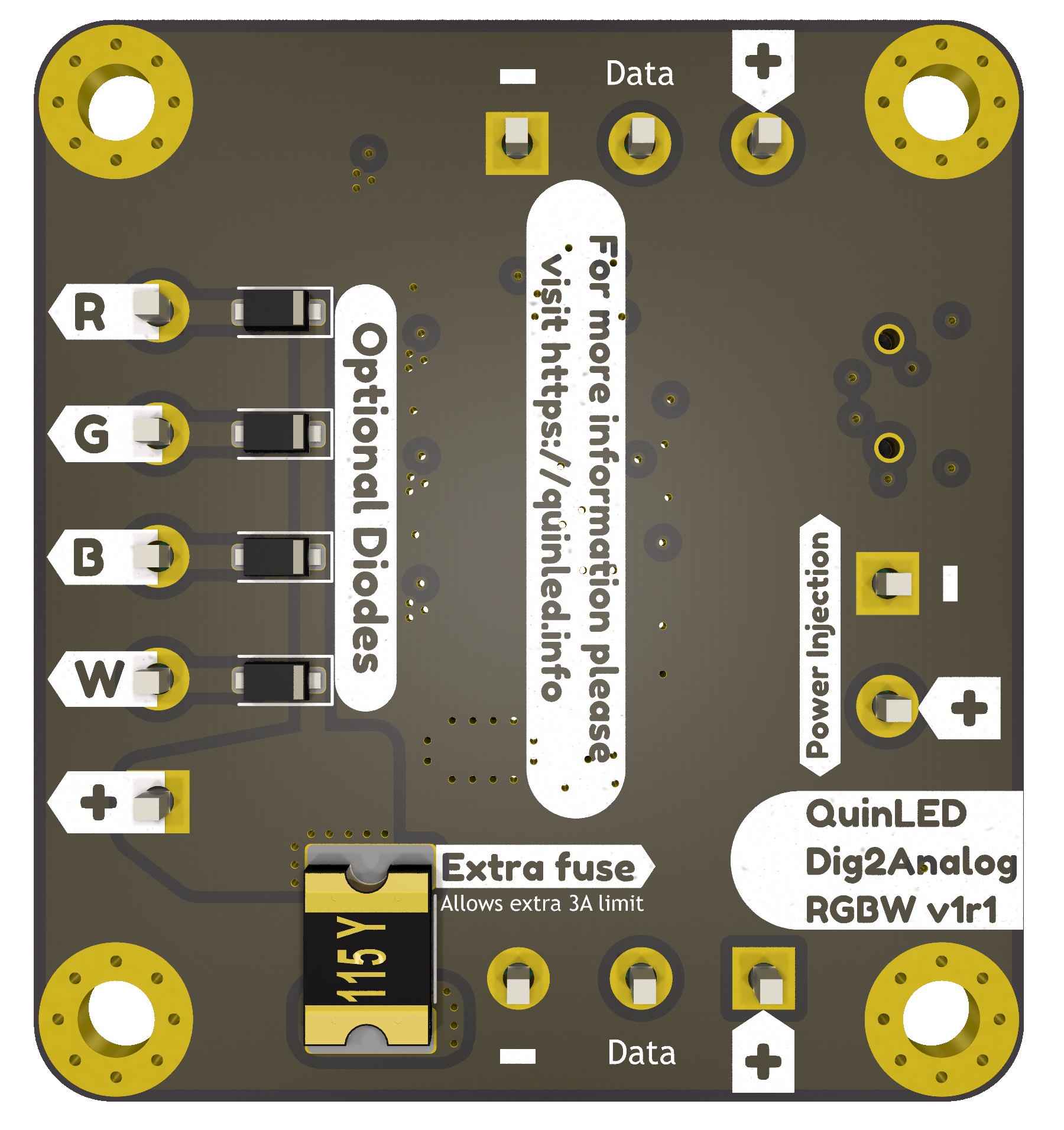
- Optional User Upgrades
-
- Can be installed by user in freewheel/flyback configuration for inductive loads
- Extra 3A fuse
- For a total of 6A output power
-
- 4x M3 size screw holes to mount the board
Screw Terminals
All screw terminals can accept up to 14AWG wire with a wire ferrule.
- 2x 3p 5.08mm for Positive – Data – GND
- 1x 2p 5.08mm for Positive – GND
- 1x 5p 5.08mm for R+G+B+W+VCC_F
- VCC_F = VCC fused