The 24V issue, information, mitigations and fixes
We’ve noticed a higher failure rate of current Dig-Uno/Quad/Octa brainboards running 24V
For a little while now I and my Discord have been seeing a trend where it seems that boards running 24V fail more often then we’d expect ( and like). This isn’t a huge volume but over the past 6 months I think we’ve done about 10 to 15 replacements where the MT3608 DC-DC converter IC on one either a Dig-Uno/Quad/Octa-brainboards has failed.
At first it wasn’t really clear what was causing these failures and because of the limited number of failures it didn’t really stand out too much but over the last month we do feel it might need more attention then it has had. Hence this article and an official replacement program. I have extended the warranty for this particular issue and if you’ve had a board die because of this exact cause I will replace them up to 1.5 years old (18 months). You can find the form here (only intended for dead boards from this issue!).
But that doesn’t really help you if you are currently running these boards and while occurrences are limited (and you will get a replacement board if it happens within 1.5 years of purchase), I can understand you wanting to mitigate the issue before it becomes a problem potentially down the road.
My deepest apologies for these issues, I (with QuinLED) strive to make excellent hardware for an affordable price, sadly this time an issue has snuck in and we’re trying to deal with it the best way we can!
If you are unsure if you are affected, would like to ask questions or discuss this, please come to the Discord server and ask in the #quinled-24v-issue channel.
This only (potentially) affects boards running with 24V, 5v and 12V are not affected!
Affected boards:
- QuinLED Dig-Octa Brainboard v2r2/v2r3
- QuinLED Dig-Uno v3.5r3
- QuinLED Dig-Quad v3.5r3
Index
Mitigation
Dig-Octa Brainboard
Dig-Uno
Dig-Quad
Revival
(Options for broken boards (outside of warranty))
USB-C “trick”
External buck converter on 5V pin
Fix/Repair
Replacing the IC on the board
Preventing the issue from occuring
Dig-Octa Brainboard v2r2/v2r3
For the Dig-Octa system there are multiple ways to mitigate this issue.
Option 1: Lowering voltage slightly
If you are running with a powerboard because of all protections in place there is already a lot of voltage drop happening before the input power reaches the DC-DC circuit on the brainboard. We recommend lowering input voltage to somewhere around 22V and this should fully mitigate the issue and keep the board running without a problem for years.
Option 2: Disconnecting QPowerPost
The second option would be to disconnect the positive pole of QPowerPost and feeding the brainboard directly with 5V over USB-C or 5V/12V using the orange input connector. This workaround also works if you are running the board without a powerboard.
You can use either or both the Orange input connector and the USB-C input connector to provide the board with power.
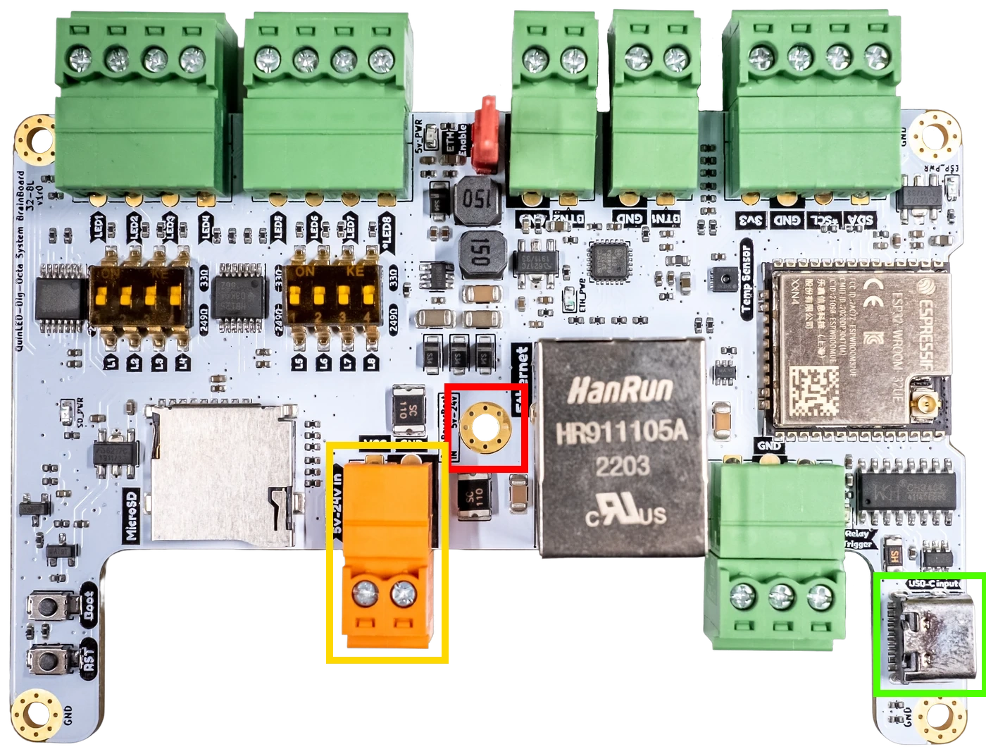 Red box is the QPowerPost positive connection, remove the screw and the post underneath
Yellow box is the 5V/12V power input connection
Green box is the 5V USB-C power input connection
You can do this using:
- A second power supply near the board
- Add a 5V or 12V power supply, can be a phone adapter for USB-C or something generic for 5V/12V input on the orange plug on the brainboard
- A little buck-converter from the main 24V power supply and convert the 24V to 5V for the USB-C input for instance
- You can connect the buck-converter to the orange terminal on the Powerboard
- A converter with at least 5V 2A output is recommended
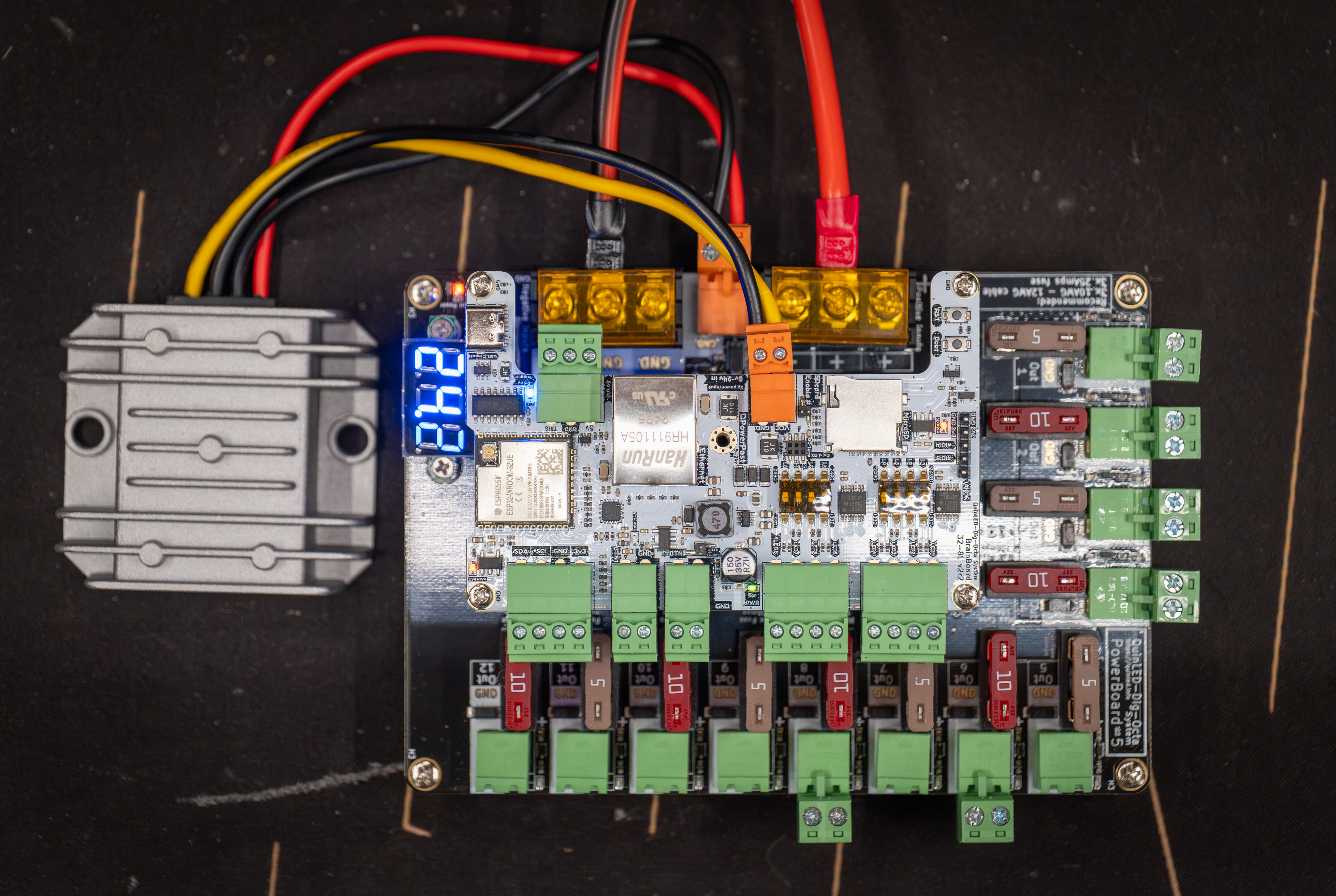 Using the orange output on the powerboard to feed the buck-converter and with the 5V/GND out of the buck-converter powering the brainboard using the orange input terminals (QPowerPost middle pole removed!)
Dig-Uno
For the Dig-Uno a fix can be applied by cutting a component off the board. The board is designed to support 2 power inputs, main and VEXT. By default these are “linked” together using diodes so they can’t backfeed each other. You can however remove the component that links the main input power to the onboard electronics and then feed the board using a seperate power supply or buck-converter from the main power supply, effectively powering the onboard electronics from VEXT vs the main power supply which can then remain at 24V nominal.
To do this you can either desolder and remove the protection fuse (highlighted with a yellow box below) or the diode (highlighted in the red box below). Removing either will cut off the onboard electronics and only allow it to draw power from the VEXT input pins. Removing the diode is by far the easiest since you can just cut it with some snips, even if that accidently removes the pads, that’s no problem. Generally you should be able to cut it off pretty easily.
If you were already running a second power supply (5v/12V) for the VEXT feature to use together with a relay, removing that diode or fuse is the only thing that needs to be done and it will permanently solve the issue and prevent it from becoming an issue in the future.
24V -> 5V buck converter on Aliexpress (something with at least 5V 2A output is recommended)
Wago 2p straight through block on Aliexpress
Male to female dupont wires on Aliexpress (I use red and black silicone version)
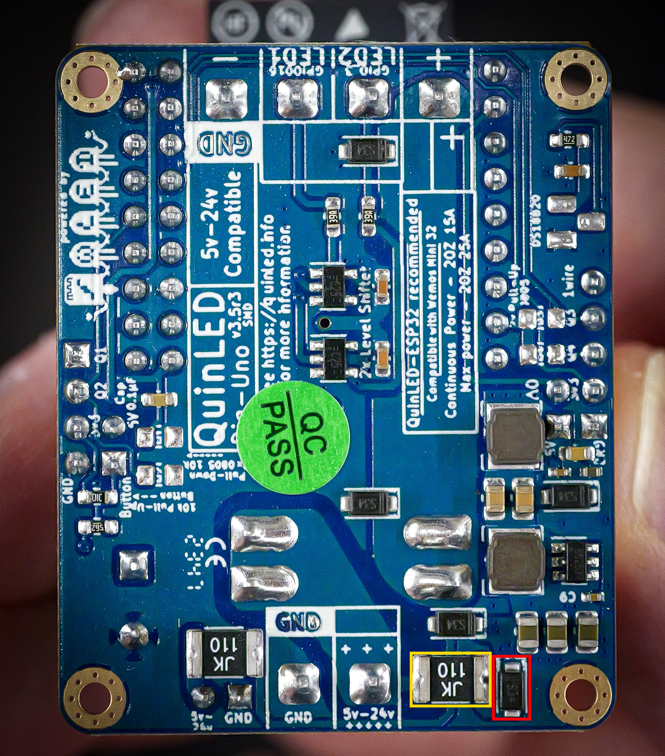 Overview of backside of the Dig-Uno v3.5r3 | Yellow is fuse | Red is diode
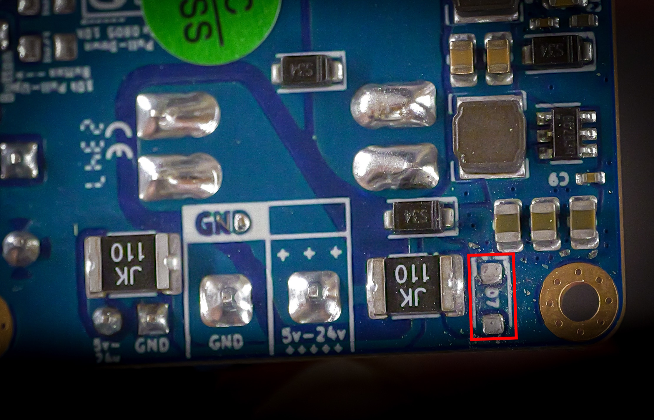 Diode (red box) cut with legs cut off the pads
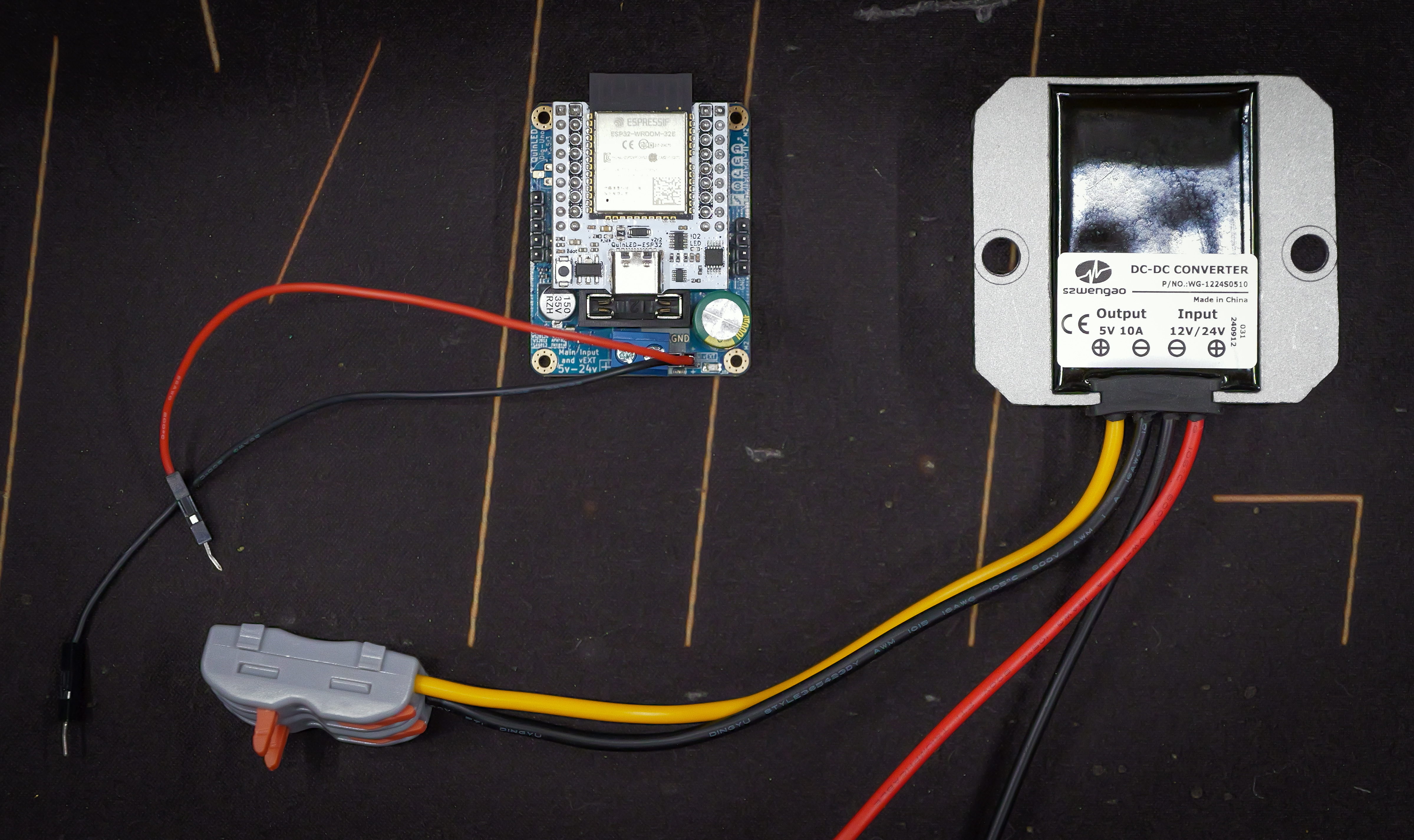 Connection diagram with buck-converter to VEXT input
(You connect the yellow wire which is 5V out to the red I used for the positive input of the VEXT connection)
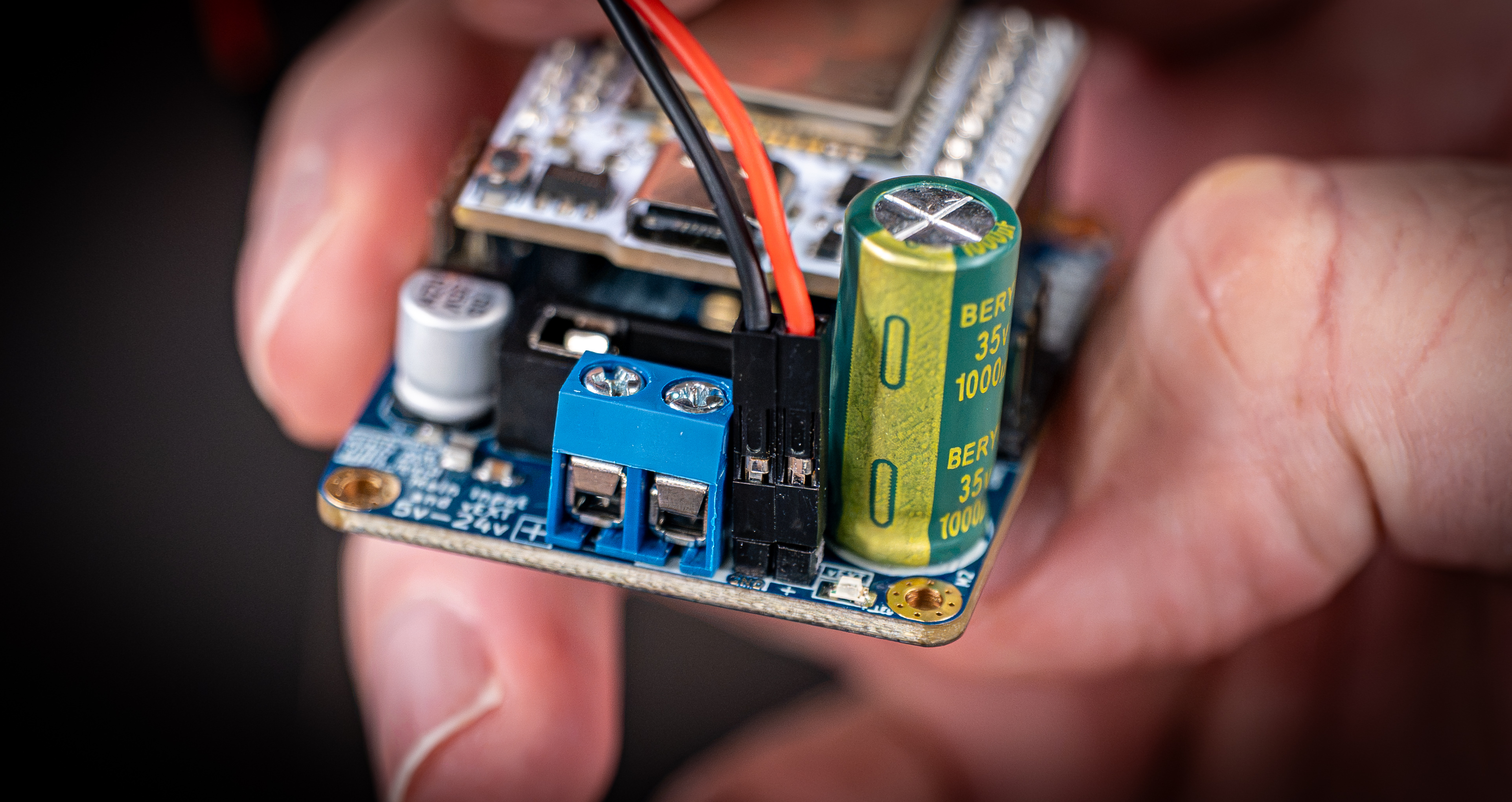 Close up of the 2.54mm dupont connections on the board, note the GND and + markings.
Dig-Quad
For the Dig-Quad a fix can be applied by cutting a component off the board. The board is designed to support 2 power inputs, main and VEXT. By default these are “linked” together using diodes so they can’t backfeed each other. You can however remove the component that links the main input power to the onboard electronics and then feed the board using a seperate power supply or buck-converter from the main power supply, effectively powering the onboard electronics from VEXT vs the main power supply which can then remain at 24V nominal.
To do this you can either desolder and remove the protection fuse (highlighted with a yellow box below) or the diode (highlighted in the red box below). Removing either will cut off the onboard electronics and only allow it to draw power from the VEXT input pins. Removing the diode is by far the easiest since you can just cut it with some snips, even if that accidently removes the pads, that’s no problem. Generally you should be able to cut it off pretty easily.
If you were already running a second power supply (5v/12V) for the VEXT feature to use together with a relay, removing that diode or fuse is the only thing that needs to be done and it will permanently solve the issue and prevent it from becoming an issue in the future.
24V -> 5V buck converter on Aliexpress (something with at least 5V 2A output is recommended)
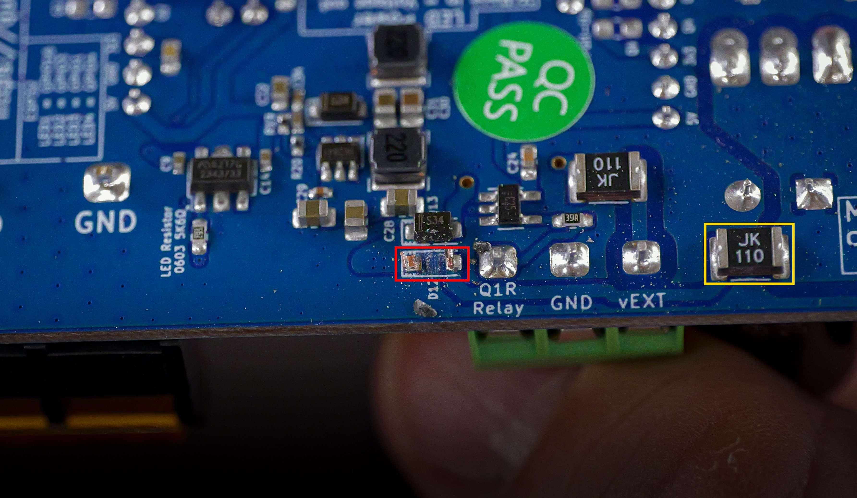 Dig-Quad with diode (red box) cut, no real cleanup like on the Dig-Uno above.
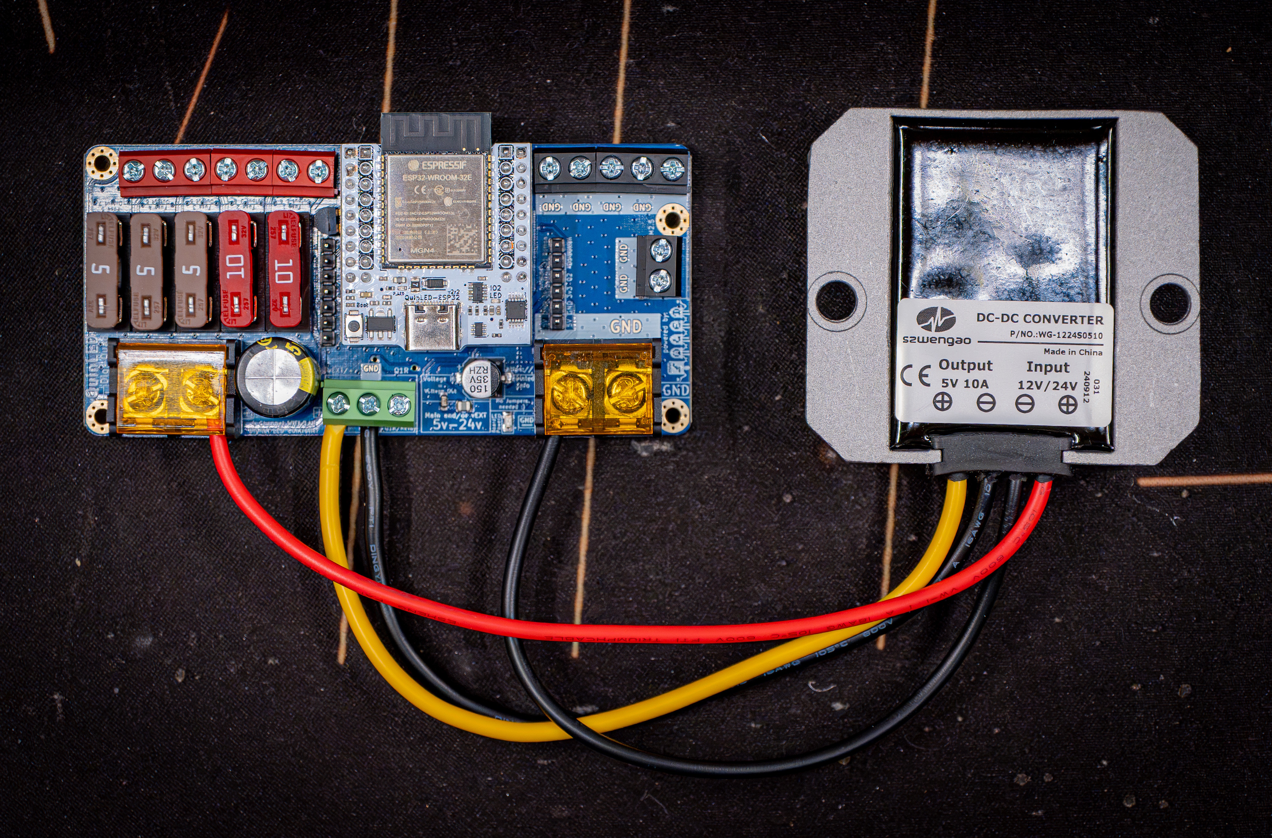 Dig-Quad v3.5r3 with buck-converter on VEXT input
(Yellow on the buck converter is the 5V positive output)
Options for broken boards to make them run again
When you board has died and it’s outside of the (extended) warranty period there are a few options you can use to still run the board. Everything on the board is basically still fine except for the DC-DC circuit. This can however be bypassed to still make use of the rest of the hardware on the board!
For both these options it’s still advised to cut the diode on the Dig-Uno and Dig-Quad as outlined above although not 100% required since the dead DC-DC IC won’t pass any power anymore.
USB-C “trick” for Dig-Uno/Quad
Some customers have reported they were able to run the board without a problem by just plugging in USB-C into the ESP32 module. Although there are diodes in place to prevent backfeeding of 5V into the board, diodes do sometimes still bleed a little bit of power, especially when the other side has no voltage present. This tiny little amount of power is enough to power the level-shifters and circuits on the board to basically restore full functionality. So you still have a level-shifted output (might not be exactly 5V but more like 4.6V or something in that range, which is still officially in range of LED ICs and better then 3.3V without a level-shifter), power distribution and fused outputs.
On the Dig-Quad this should fit without an issue on the Dig-Uno sadly this trick is harder to use since it requires a different size fuse because by default it blocks the USB-C port but see the second option below this one!
For this you can either use a second 5V power supply (like a phone charger 5v 2A recommended) or use one of the buck-converters linked above.
[photo of Dig-Quad with USB-C in connected]
Sadly this trick will not work for the Dig-Octa brainboard but see below for another option.
Feeding 5V into the board directly (with a buck-converter)
Another way of doing this is by basically bypassing the onboard circuit to feed 5V back into the board, this can be done with either a second 5V power adapter (like a phone charger with a cable with one of the ends cut off and the wires exposed) or using a small 24V to 5V buck-converter. Next to that you’ll need a 2p straight through connection (wago) block and 2 dupont style 2.54mm cables.
On the Dig-Uno and Dig-Quad there are 5V and GND headers you can use to inject this power. Below are photos of how that is connected.
Dig-Uno
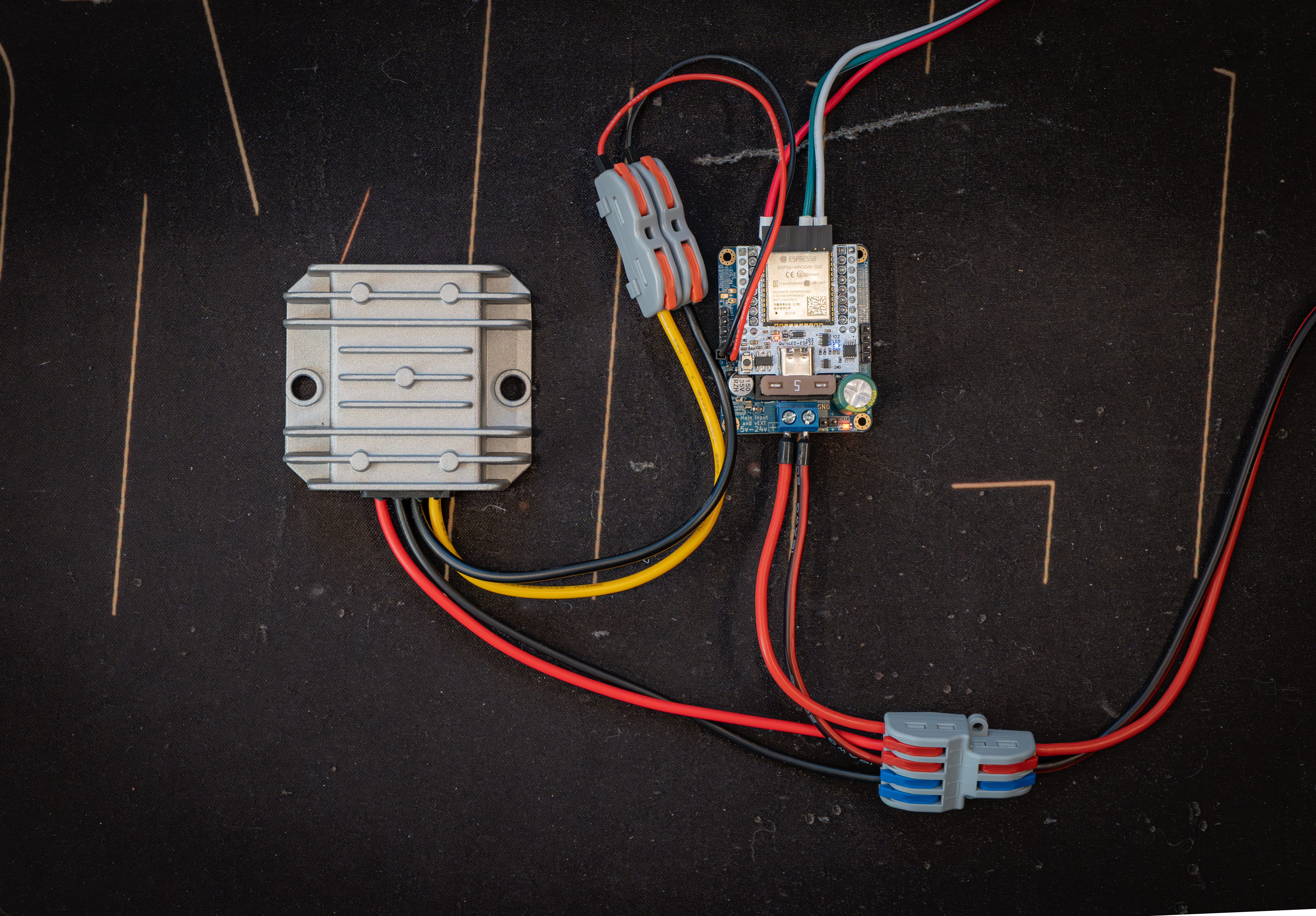 5V and GND out from the buck-converter connected into the one of the 5V and GND pins on the Dig-Uno (there are 2 sets available)
Dig-Quad
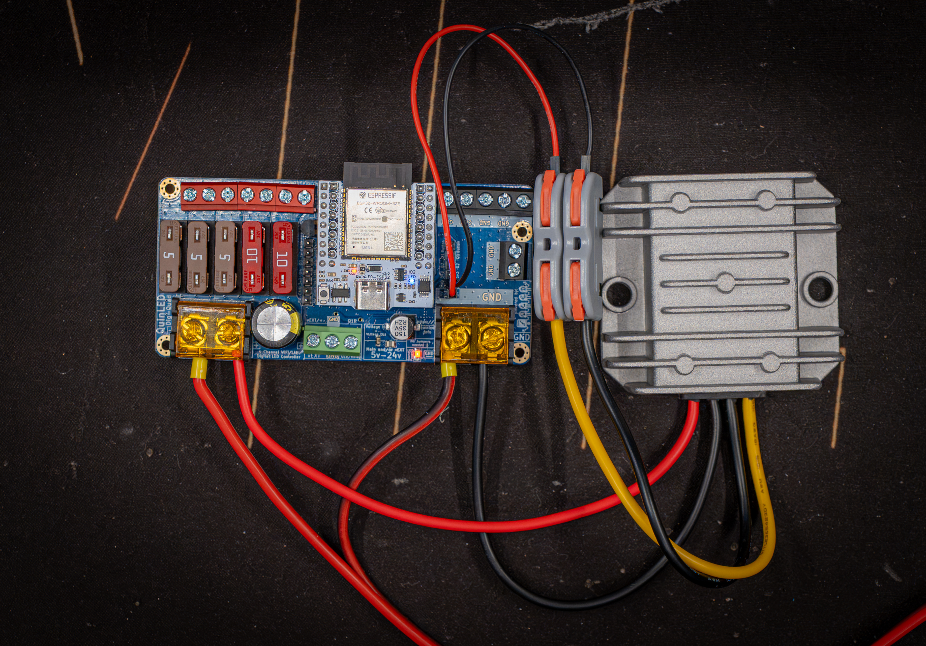 5V and GND out from the buck-converter connected into the one of the 5V and GND pins on the Dig-Quad (there are 2 sets available)
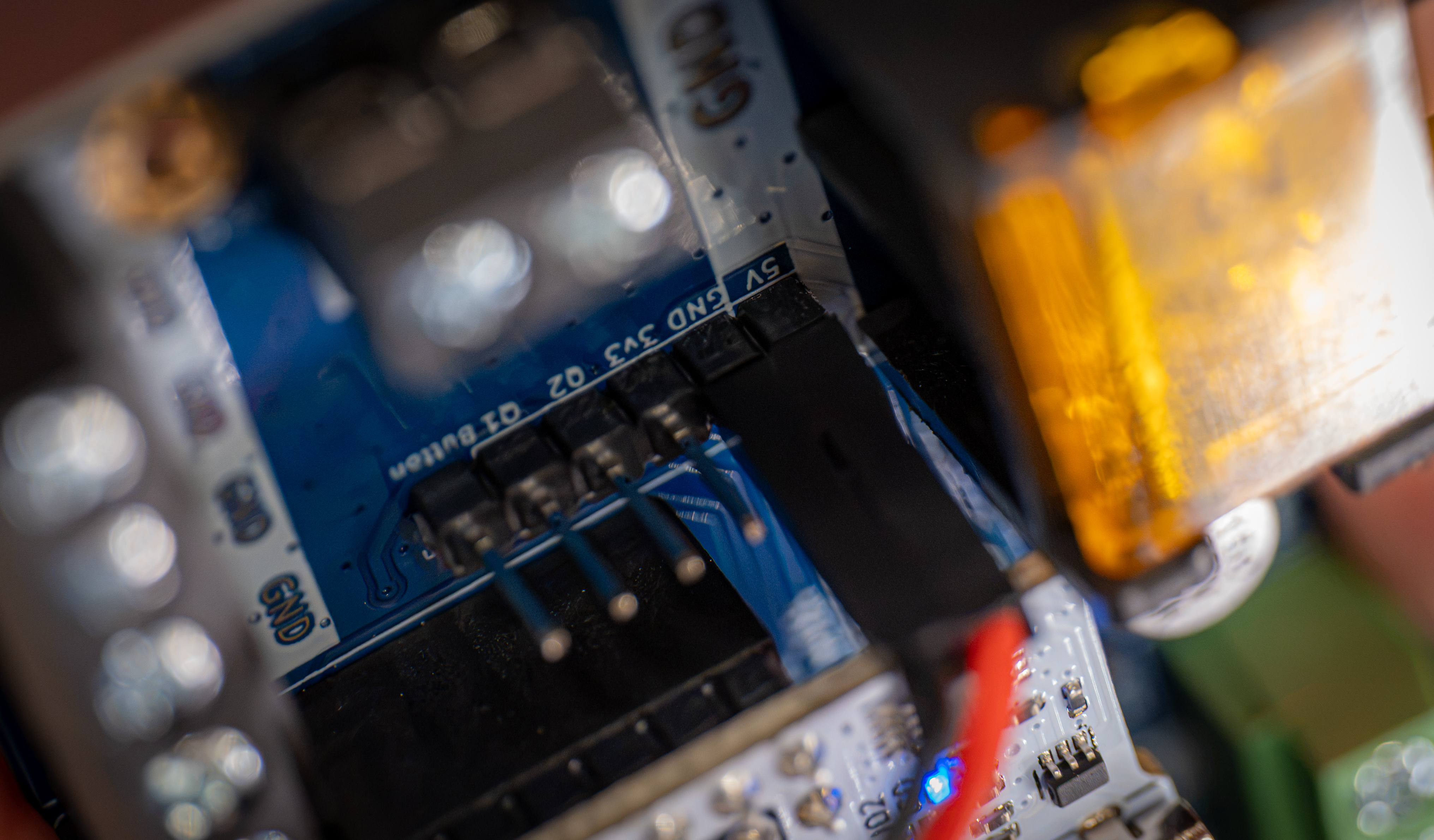 Pin headers (one set of two) available on the board to feed in 5V and GND from the buck-converter (Dig-Quad in this case)
Dig-Octa
On the Dig-Octa Brainboard you can use the relay output terminals to basically feed 5V back into the board again using either a separate 5V power supply or using a small buck-converter from 24V to 5V. Below a photo of showing this using the orange output of the powerboard to go into the buck-converter and then having it connected to the relay terminal.
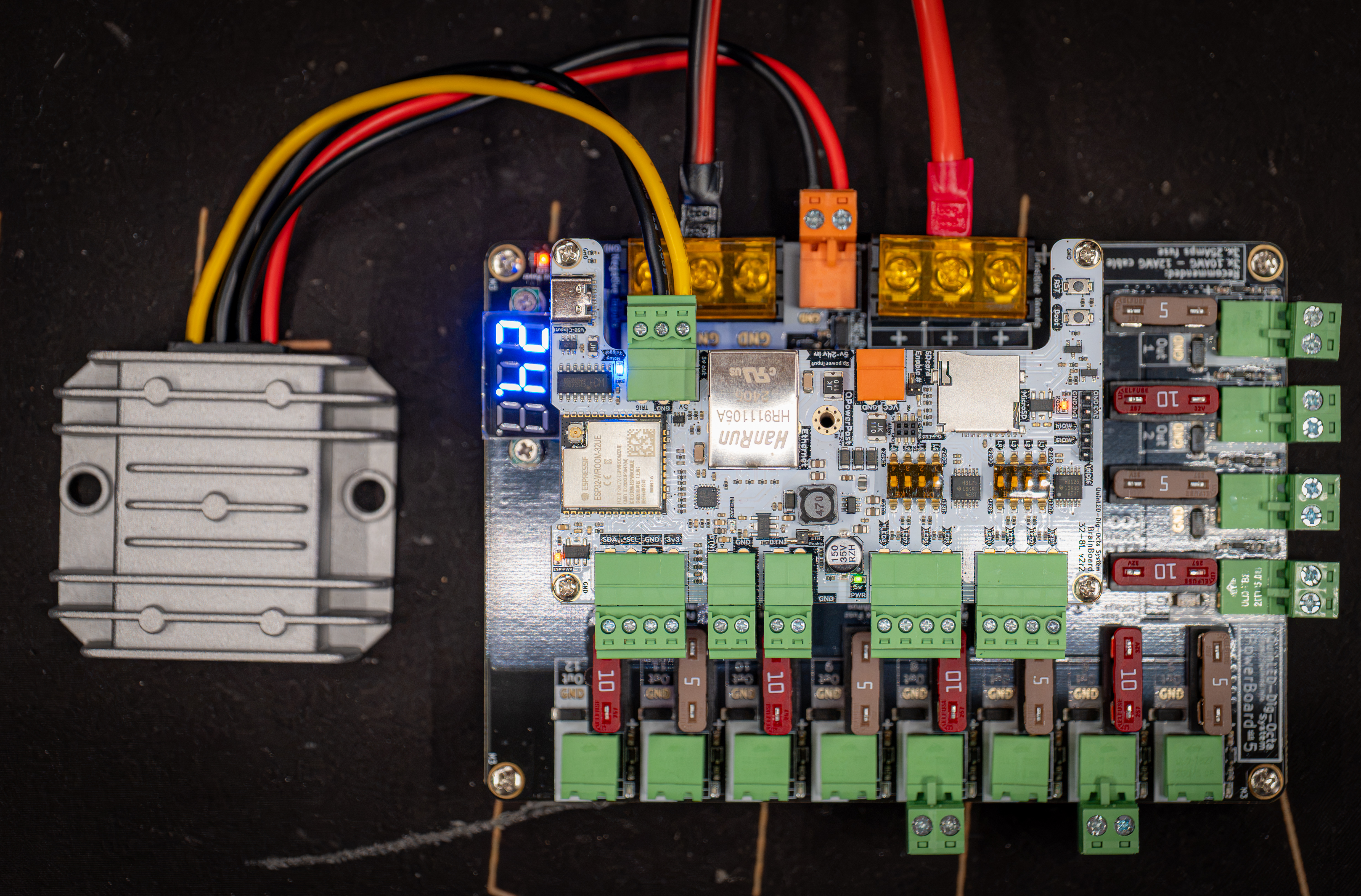 Using the Orange output on the Powerboard to feed buck-converter and then using 5V and GND output of buck converter to feed into relay terminals to power the brainboard (Middle QPowerPost disconnected!)
Your board is broken, how to repair it
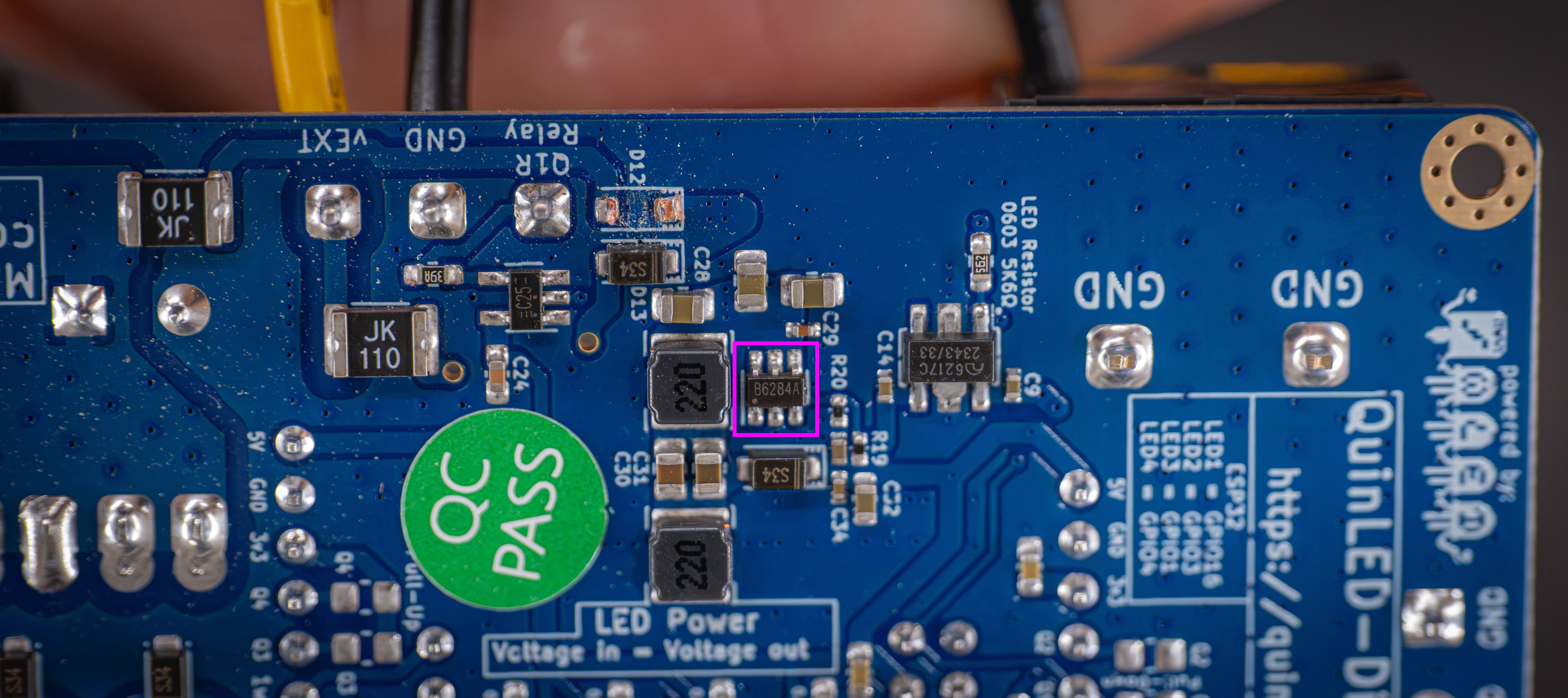
In cases where the board died, replacing the MT3608 DC-DC IC has generally brought it back to life and function perfectly again. So if your board has died and it’s beyond the (extended) warranty period, it’s worth a shot to try this!
The IC in question is the MT3608 and can be purchased from LCSC but the shipping costs might be high. It can also be acquired on Aliexpress for instance, here are 2 listings (Listing 1 | Listing 2).
Replacing should be possible using an iron or hot air but it’s a tiny IC with tiny legs so I get it can be daunting for a beginner.
- Soldering iron
- First flood the legs on both sides with leaded solder and then try and heat up one side to lift and then lift that side of the IC up until it no longer touches the board, then do the same to the other side.
- Then use solder wick to suck up all the solder that’s now on the pads
- Get the new IC, orient it correctly, tack one pin into place with solder and then solder the rest of the pads
- Done!
- Hot Air
- If you have it, add some leaded or low temp solder paste to both sides with legs
- Hit it with air to remove the chip
- Clean it up a bit, add a line of paste to each of the rows of pads
- Place the new IC (orient it correctly) and hit it with hot air again.
- Done!
Markings on the IC itself can be slightly different since it’s a date code, not a product code!
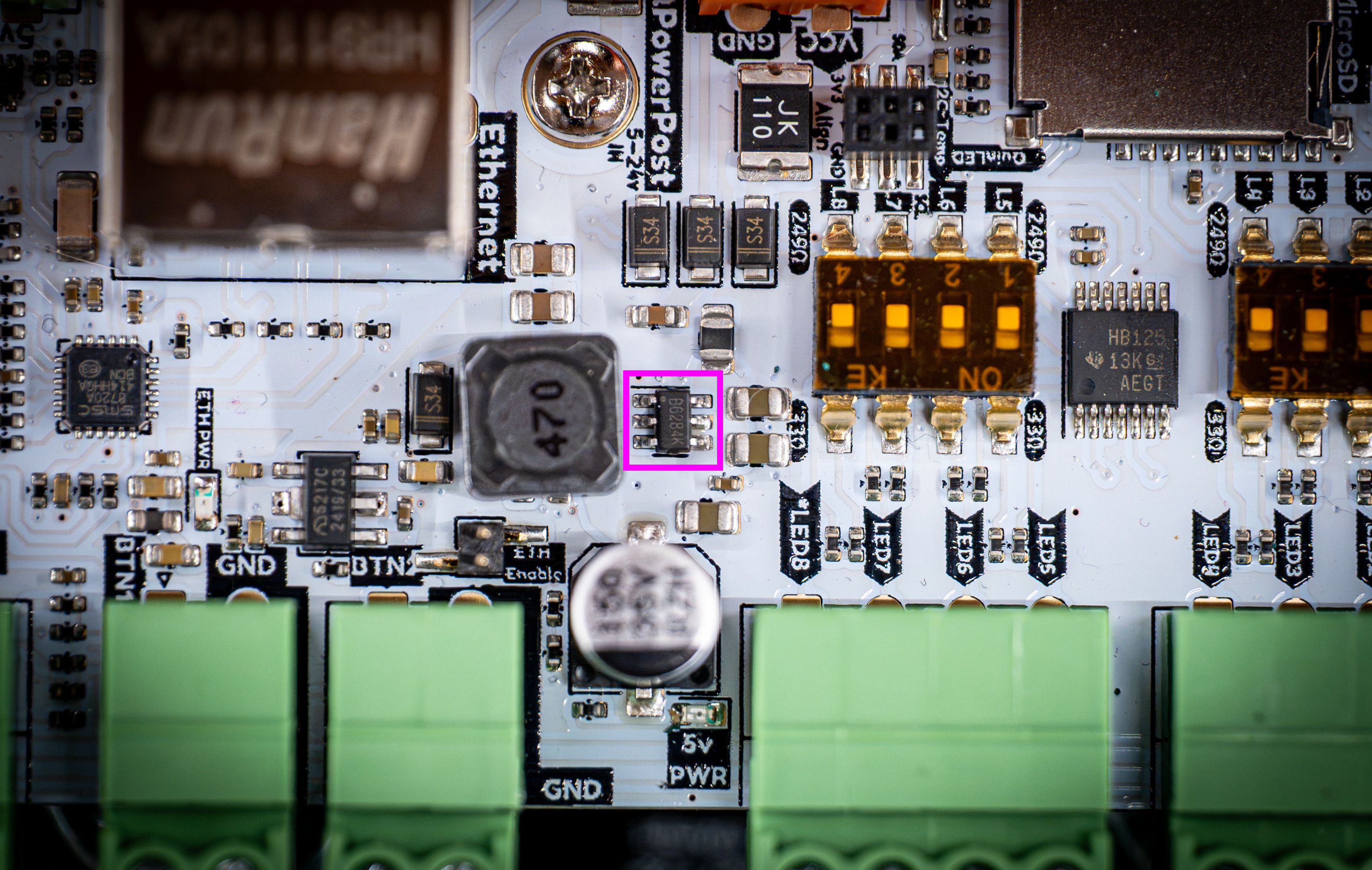
Where is the IC on the board?
Dig-Octa Brainboard
Dig-Uno
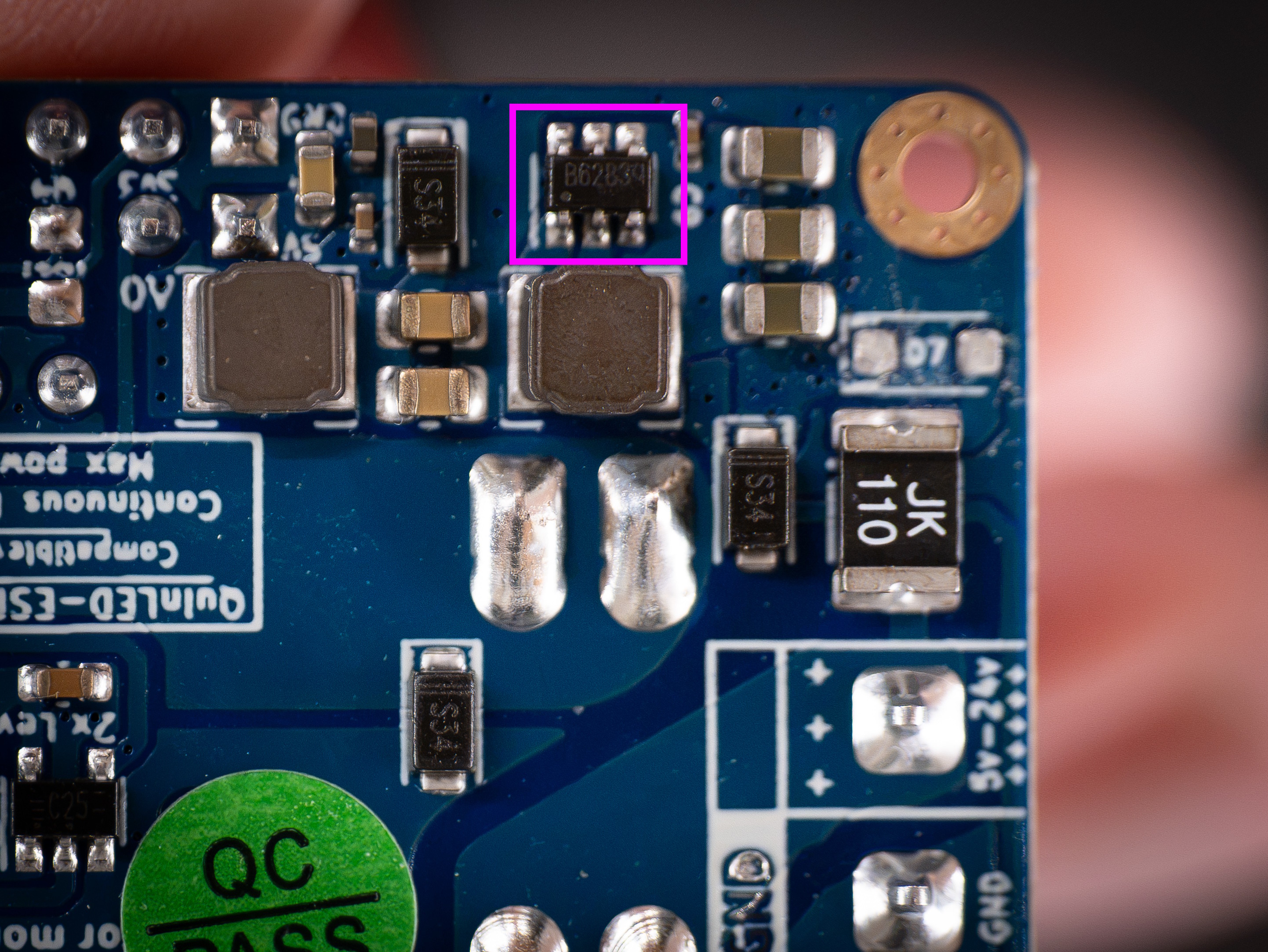
Dig-Quad