
QuinLED-Dig-Octa Relay output & Standby power
Some of the QuinLED-Dig-Octa brainboards might have a relay feature. This feature allows you to connect a simple relay board to this connection to allow turning on and off the main LED power supply connected to a powerboard for instance.
List of current boards with relay feature:
Standby power feature of brainboards
Because brainboards have been designed with allowing multiple simultaneous power connections the simplest way of providing standby power for multiple brainboards in a stack is by using a multi-port phone charger. These generally give out a decent amount of power and should have no issue keeping a few brainboards with relays alive while the big power supplies are off.
To do this connect a USB-C cable to each brainboard you wish to keep online while the main LED power supplies are turned off. It’s recommended to budget about 5v 1Amp per brainboard but average usage is more around 300mA~500mA (depending on features active).
*The same standby power feature can also be supplied over the 2p 3.81mm input connector (for instance from a POE splitter) or even both (USB-C and 2p) at the same time
Relay feature
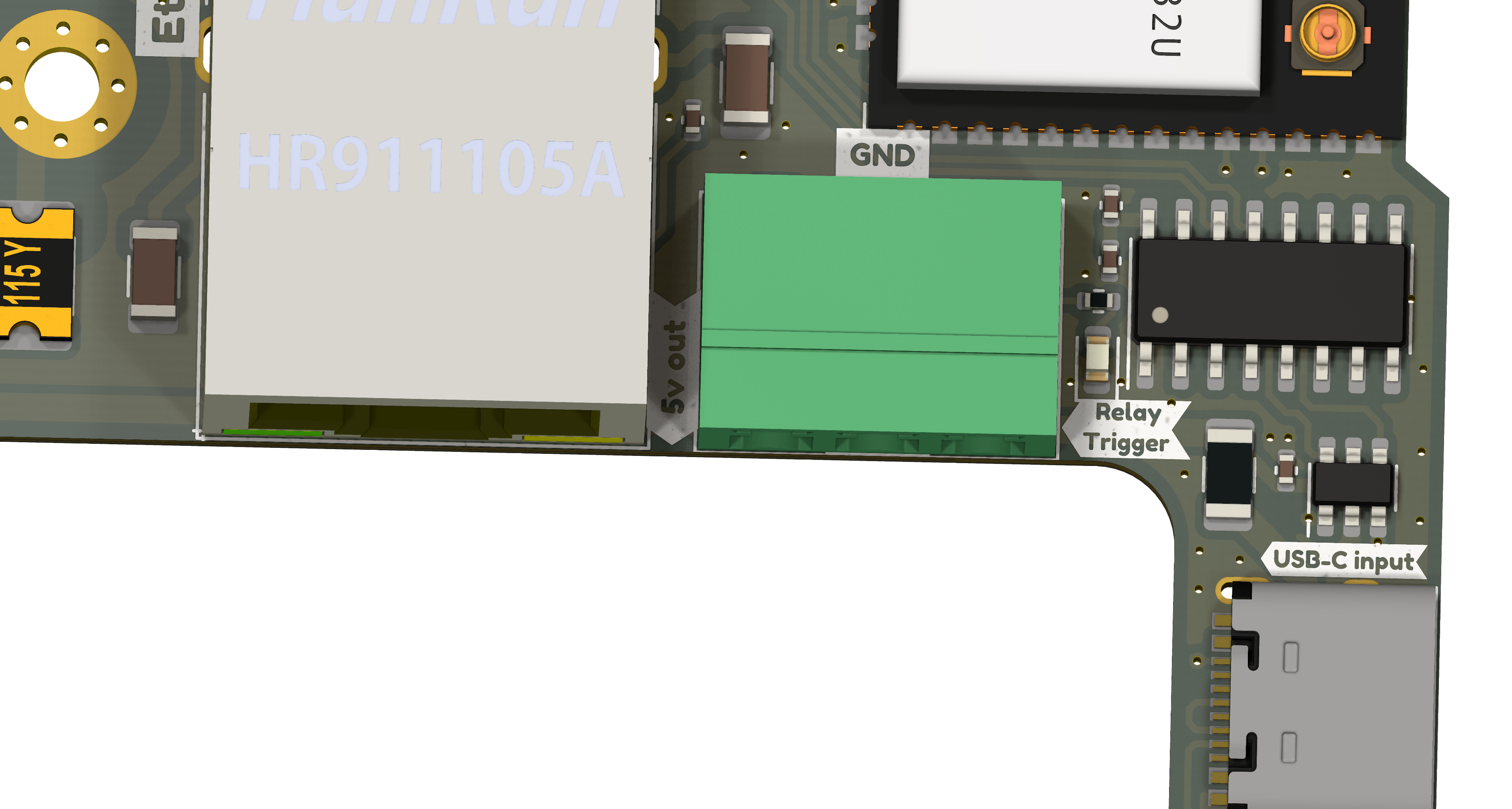
The QuinLED-Dig-Octa_Brainboard-32-8L has been designed with a relay trigger feature. This provided through a 3p 3.81mm pluggable screw terminal which delivers:
- 5.12v out (always, independent of input voltage or source) to power the relay board
- GND
- Relay trigger (5.12v signal when high)
- Connected to a GPIO pin so it can be triggered through software
- Currently at least WLED provides this feature
- Connected to a GPIO pin so it can be triggered through software
The trigger circuit has been specifically designed to allow for higher power drains (MOSFET power circuit) so can be used to run multiple relays if desired. It’s been tuned to allow relays that trigger on LOW or trigger on HIGH with providing a 5.12v trigger voltage, especially if running multiple relays it’s advised to run the relays in HIGH mode trigger if possible.
You might want to switch multiple relays with a single brainboard if you have multiple powerboards each with their own power supply, this is allowed.
Simple relay boards are often connected either using screw terminals (and then only require some simple wires) or using dupont cables (male on the brainboard side to female on the relay board generally).
*It’s advised not to run more then 4x normal 10Amp relays or 2x 30Amp relays from a single brainboard, if so desired please use external power directly from the standby power supply
[photo of relay board hooked up with terminals]
Relay on AC side advised
Since we’re dealing with huge amounts of power on the DC side of things (especially if running 5v LEDs) it’s recommended to place the relay on the AC side.
[diagram]
[photo]
This effectively kills all standby power including that of the big power supply itself. Also the amount of Amps are much much lower:
- 250 watt
- @5v = 50Amps
- @110v = 2,27Amps
- @230v = 1,08Amps
Thus it’s much more effective cutting the power supply on the AC side and generally advised.