24v power distribution for 5v LEDs
Why look for a different solution?
A lot of people look into doing large projects with 5v ws2812b “neopixel” or 5v sk6812 addressable LEDs and while these LEDs are truly a revolution in regards to what is possible to do with them, their 5v nature also make them inherently hard to use in larger scale projects because of the massive amounts of current involved or the effect that causes which is often referred to as “voltage drop”.
Alternative 12v and 24v LED chips
There are of course alternatives in the market now such as 12v ws2811 or 12v ws2815 or even 24v versions, but each of those has inherent downsides using them.
On a strip ws2811/sk6812 is per 3 addressable if it’s 12v or per 6 addressable if it’s 24v. The reason for this is because the the voltage needs to be divided over 3LEDs for 12v and 6LEDs for 24v to drop it down to about what the LEDs needs. This can be an acceptable down-side in some larger scale projects where the distance between the viewer and the LEDs is a bit further away for instance. Also new variants with 12v 96LEDs/m ws2811 are interesting since with their per 3 addressable LEDs such a strip still have the same amount of addressable zones as 5v ws2812b 30LEDs/m for instance.
All these options are listed in my LED strip selection guide!
But a lot of people prefer to have their LEDs per 1 addressable and for those, these higher voltage versions are not an option so let’s see if there is a different solution possible.
12v ws2815
12v ws2815 is unique in that regard, on a 12v strip it’s still per single LED addressable. The current version does this by using an internal LDO per LED package which basically “burns off” the excess voltage. This comes at the cost of efficiency (and price), where for a 5v ws2812b or 12v ws2811 strip if you select 100% Red you only use the power those red LEDs need, with ws2815 basically any color running at 100% will use the same amount of power as 100% RGB white which can also clearly be seen in my real-world LED power usage sheets.
This option is also listed in my LED strip selection guide!
Still, with that said, for a lot of installs this can still make sense and reduce the power injection wiring needed vs the same amount of 5v LEDs! But ws2815 is still less suited then 12v ws2811 for instance for large scale projects because of the mentioned higher power draw (in part again needing thicker wires).
The problem is power distribution
Video Series
Initially all this was talked about and tested during 2 livestreams (Stream 1, Stream 2). After that I have also made cut up versions and turned that into a 3 part series:
Part 1 – 3: Why is using 5v over longer distances an issue?
Part 2 – 3: Testing buck converters, can they handle the load?
Part 3 – 3: Building the full setup, does it work?
Some of the information of this article is in the videos, but not all of it, so if possible, I’d suggest to at least watch the cut-up series and read the article!
Product links
✨ QuinLED-Dig-Quad Pre-Assembled: https://quinled.info/pre-assembled-quinled-dig-quad/
✨ QuinLED-Data-Booster(-Maxi): https://quinled.info/quinled-data-booster-for-sale/
✨ LED strip buying guide: https://quinled.info/2019/06/03/what-digital-5v-12v-rgbw-led-strip-to-buy/
✨ Tools and Equipment used page: https://quinled.info/2018/10/01/tools-and-equipment/ (including wiring, etc.)
🛒 Plastic Housing DC-DC converter: https://s.click.aliexpress.com/e/_9QUDOn
🛒 Metal Heatsink DC-DC converter: https://s.click.aliexpress.com/e/_ACEEQL
Why is power distribution a problem?
To highlight this, let’s take a look at an example of my “power injection calculation” livestream:
5v ws2812b 60LEDs/m
2x300LEDs = 600LEDs total
    SEE POWER USAGE CHARTS: https://quinled.info/2020/03/12/digital-led-power-usage/
    Max power = 130w
    Project power usage = 65w
    65w / 5v = 13 Amps
Wait, what cables do I need for this?!
  (https://www.rapidtables.com/calc/wire/voltage-drop-calculator.html)
    Drop acceptable = 10% = 0,5v so 4,5v acceptable
  front = 1m/3ft      3,25 Amps	  minimum 20 AWG	0.5mm2
  middle = 6m/19ft    6,50 Amps	  minimum 13 AWG	2.6mm2
  end = 11m/35ft      3,25 Amps	  minimum 14 AWG	2.0mm2
Using this example you can see that even for a simple setup, even with calculating with 50% nominal usage, you are going to need 13AWG and 14AWG cable to do power injection runs, otherwise you’d already have too much voltage drop on just those cables to be of much use anymore, for a large part this has to do with the length of these cables. The longer a cable becomes the more copper you need to prevent the resistance of the cable already costing too much energy.
When doing power calculations for cabling I use the rule that 10% is acceptable to lose on just the cables, but especially with 5v LEDs, not more then that, which means you only have 0,5v to loose, and that’s not a lot!
Using a higher voltage for transport
The reason of this post is to look at using a higher voltage for the transport and then converting it down to 5v where it’s needed. In this case I generally take 24v as the voltage since this is fully compatible and supported on the current QuinLED-Dig-Uno and QuinLED-Dig-Quad boards meaning you can still use your controller as is, including power distribution, fusing, etc..
24v already makes a really big difference:
10Amps at 5v = 50w
50w / 5v = 10Amps
50w / 24v = 2,08Amps
That means it’s almost a 5 times reduction in the Amps that need to be transported.
Let’s say we need to transport those 50w over a 10m cable with max 0,5v drop:
(using: https://www.rapidtables.com/calc/wire/voltage-drop-calculator.html and a max drop voltage drop of 10%)
10Amps at 5v over 10m needs at least 10AWG or 5,2mm2 cable
2,08Amps at 24v over 10m needs at least 22AWG or 0,36mm2 cable
As you can see, that is a massive massive difference. Where 10AWG is a completely unwieldly and very costly copper bar basically, 22AWG is very easy to use and quite cheap all while delivering the exact same amount of power to our end goal, the LEDs.
Buck Converters
But if you use a 24v power supply and use it as the transport voltage, although the QuinLED-Dig controllers can use that natively, the LEDs certainly can’t so we need something to change the voltage from 24v to 5v for them to use. This is where high power buck converters come in, these (non-isolated) buck converters can be had up to 40Amps while also delivering up to 95% efficiency while staying relatively cheap, making them a very interesting solution.
They are of course an added cost but one that will quickly pay for itself looking at the difference in cable sizes that can be used in the above examples. A decent 24v to 5v buck converter can be had for about 15$.
Even better, more drop acceptable!
Even better, using buck converters you can in part even let go of the normal 10% maximum voltage drop rule. When normally running power wires and using 5v as the power supply and the LED also wanting 5v you want to minimize drop as much as possible, hence the 10% rule in that regard. But using buck converters to 5v, as long as the input voltage is slightly above that, we’re basically good to provide a stable 5v for our LEDs!
Now don’t go too crazy in that regard, all loss is a loss and will result in high power draw and heat then needed. But if the buck converter gets 22v or even say 18v, that is no problem at all and the buck converter can easily make a stable 5v out of that!
Scenario compare
900LEDS 5v vs 24v distribution
Let’s take a look at the scenario of using 15m or 3x ws2812b 60LEDs/m or 3x 300 LEDs in total. Following my own guidelines (as can be seen in the power injection livestream) we need a front injection, then 2x middle injections and an end injection so that each 300LEDs will have a front + end injection basically.
5v distribution scenario
Doing the math for that we see the following for the 5v scenario:
60LEDs/m - 3x300LEDs = 900LEDs total
    SEE POWER USAGE CHARTS: https://quinled.info/2020/03/12/digital-led-power-usage/
    Max power = 195w
    Project power usage = 97,5w (will use 100w in calculations)
    100w / 5v = 20 Amps
      Edge injection point = ~4Amps max
                        Middle injection point = ~8Amps max
  1x injection = total fail
  1x injection !middle! = total fail
  2x injection (front + end) = total fail
  3x injection (front + middle + end) = Can work (4 + 8 + 4 = 16Amps)
        4x injection (front + middle + middle + end) = ok

  How much power do I need where?
  20Amps divide over 4 injections
  2x are edge injections, 2x middle injection
  20Amps/2 = 10 Amps
    Front/End = 1/2 of middle point = 5 Amps or 2,5Amps each
        That means it will likely divide as following:
                Front=   5v 2,5Amps
                Middle = 5v 8A
                Middle = 5v 8A
                End =    5v 2,5A
                TOTAL =  5v 21A

  Will my LEDs stay smooth?!
  Total LEDs = 900
    LED Protocol limits
      ~500LEDs = 60FPS/updates per LED per second
      ~600LEDs = 55FPS/updates per LED per second
      ~1000LEDs = 30FPS/updates per LED per second
      ~1500LEDs = 15FPS/updates per LED per second
    900 falls below default WLED framerate of 42FPS, a second data connection after 600LEDs is recommended! This
                can be done with both the QuinLED-Dig-Uno or QuinLED-Dig-Quad (recommended because of power injection needed)

  Wait, what cables do I need for this?!
  (https://www.rapidtables.com/calc/wire/voltage-drop-calculator.html)
    Drop acceptable = 10% = 0,5v so 4,5v acceptable
  front = 1m/3ft      2,5 Amps	 minimum 20AWG  0,5mm2
  middle = 6m/19ft    8 Amps     minimum 12AWG  3,3mm2
  middle = 11m/36ft   8 Amps     minimum 10AWG  5,2mm2
  end = 16m/35ft      2,5 Amps	 minimum 13AWG  2,6mm2
24v distribution scenario
Doing the math for that we see the following for the 24v scenario:
60LEDs/m - 3x300LEDs = 900LEDs total
  SEE POWER USAGE CHARTS: https://quinled.info/2020/03/12/digital-led-power-usage/
  Max power = 195w
  Project power usage = 97,5w (will use 100w in calculations)
  100w / 5v = 20 Amps
    Edge injection point = ~4Amps max
                Middle injection point = ~8Amps max
  1x injection = total fail
  1x injection !middle! = total fail
  2x injection (front + end) = total fail
  3x injection (front + middle + end) = Can work (4 + 8 + 4 = 16Amps)
        4x injection (front + middle + middle + end) = ok

  How much power do I need where?
  20Amps divide over 4 injections
  2x are edge injections, 2x middle injection
  20Amps/2 = 10 Amps
    Front/End = 1/2 of middle point = 5 Amps or 2,5Amps each
        That means it will likely divide as following:
                Front=   5v 2,5 Amps   24v 0,5Amps
                Middle = 5v 8 A        24v 1,6A
                Middle = 5v 8 A        24v 1,6A
                End =    5v 2,5 A      24v 0,5A
                TOTAL =  5v 21 A       24v 4,375A

  Will my LEDs stay smooth?!
  Total LEDs = 900
    LED Protocol limits
      ~500LEDs = 60FPS/updates per LED per second
      ~600LEDs = 55FPS/updates per LED per second
      ~1000LEDs = 30FPS/updates per LED per second
      ~1500LEDs = 15FPS/updates per LED per second
    900 falls below default WLED framerate of 42FPS, a second data connection after 600LEDs is recommended! This
                can be done with both the QuinLED-Dig-Uno or QuinLED-Dig-Quad (recommended because of power injection needed)

  Wait, what cables do I need for this?!
  (https://www.rapidtables.com/calc/wire/voltage-drop-calculator.html)
    Drop acceptable = 15% with 24v = 3,6v drop acceptable (~20v left)
  front = 1m/3ft         0,5 Amps      minimum 20AWG    0,5mm2
  middle = 6m/19ft       1,6 Amps      minimum 20AWG    0,5mm2
  middle = 11m/36ft      1,6 Amps      minimum 20AWG    0,5mm2
  end = 16m/35ft         0,5 Amps      minimum 20AWG    0,5mm2
 *Because of wire ratings it is best to use minimum 20AWG but theoretically 24AWG would already have sufficed!
Comparing 5v vs 24v scenario cabling needs
Conclusion of the above examples is that in the pure 5v scenario you need cables that are 10AWG or 5,2mm2 which are quite thick and very expensive cables, especially at the lengths (11m/36ft) needed! Looking at the 24v scenario with buck converters it turns out we only need 24AWG or 0,2mm2 cable which is quite a bit easier to work with and much much less expensive! *Because of official wire ratings and suggested fusing (see down below) I’d recommend not using smaller wires then 20AWG in a real-world project.
If you are looking to do a large scale project with 5v LEDs to keep it single LED addressable, using buck converters and a higher transport voltage (such as the 24v suggested) seems to be the only sane choice.
Not all setups are the same
Now not all setups are the same, the above scenarios assume you are laying out the LED strip in a single long line. Often though you’ll be wrapping a room or garden or something like it and thus at some point the injection points will start becoming closer to the distribution point again making the setup a bit more viable maybe. Still, if that’s going to be the case in your scenario, I can’t know.
Schematic overview
I’ve tried to create a schematic overview of how to hook it all up! (click the picture for a larger version)
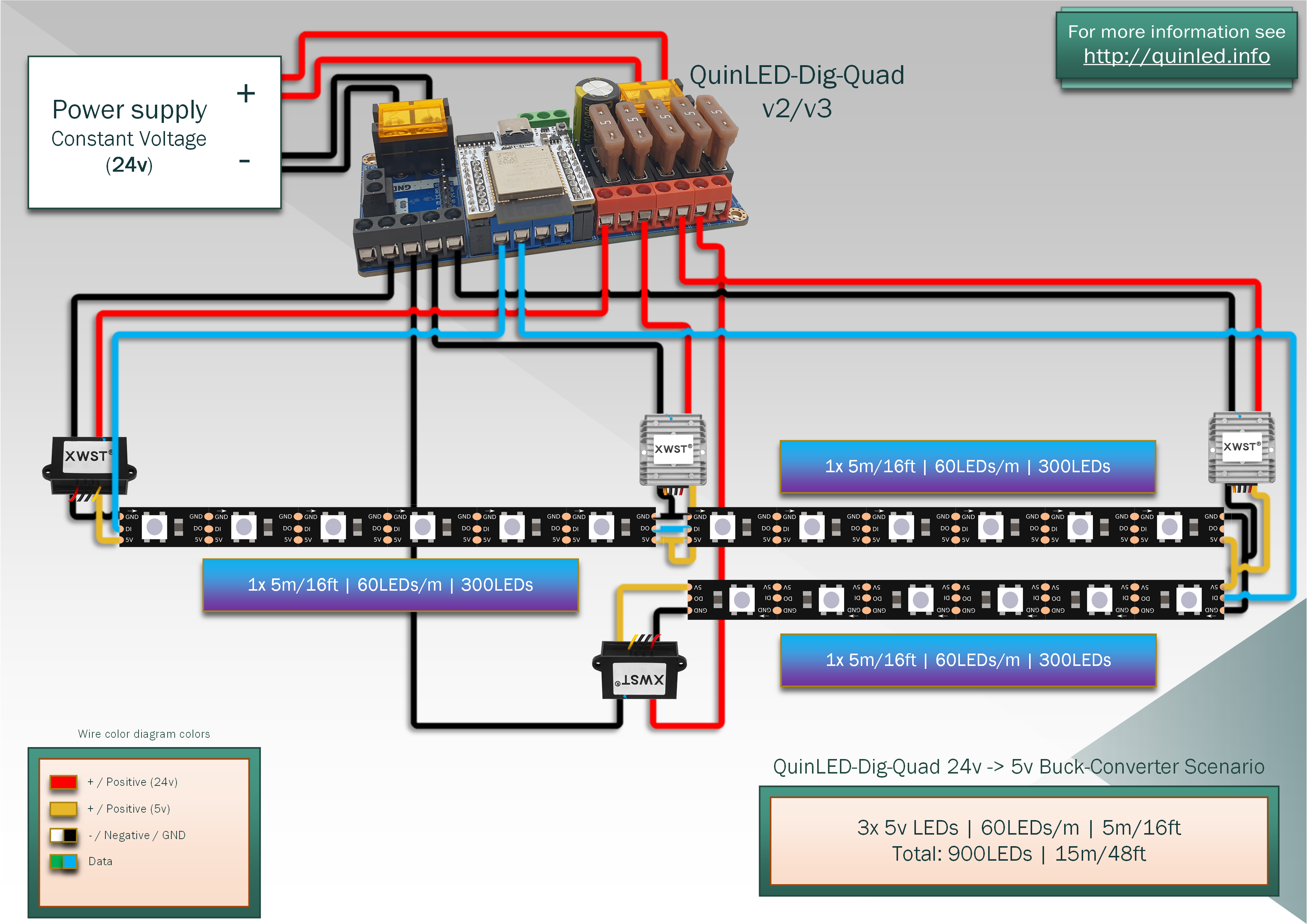
Possible dangers
(connected positive lines)
During the video tests one of the things we looked at where the dangers of keeping the positive lines of all buck converters connected together. Generally this is explicitly NOT advised since the converters will start to load share and will do so by sending the most load to the highest voltage source. And while this might work “ok” in some situations, especially in a failure scenario (wire or buck converter) one of them might get a much higher load then they where designed for and create a dangerous (fire) situation.
But….. with the buck converters spread out 5m apart and only linked together using the LED strip this situation might be less dangerous that is generally assumed. This is because the copper traces on the LED strip generally have a pretty high resistance which in turn will limit the amount of power that can be drawn from a single point and showing up as the “voltage drop” issue (this is why we’re doing all these complicated things in the first place!).
During real-world testing, pulling cables or buck-converters never ended in a scenario where it became dangerous. Also in the case of using a QuinLED-Dig-Quad for instance, all power lines towards the buck-converters are fused and if done appropriately no single point can draw more power then it is calculated to do, otherwise popping the fuse and cutting it off.
Possible to overload a converter
My advice, if you are building a setup such as this, upgrade each buck converter one level above what it needs. So a point that should draw up to 5Amps (edge connection for example), give it a 10Amp buck converter and for a middle point for instance which 10Amps generally would be enough, give it a 15Amp buck converter.
Also make sure to give the converters a little bit of room for cooling. If you are going to be putting them in a closed box, de-rate it’s rating by at least 50% and if possible, test for at least a few hours to see what temperature it becomes during a worst case scenario!
Fuse each line correctly
Then scale fuses appropriately:
10Amp @ 5v is 50w max, 50w/24v = 2,08Amps so give it a 3Amp fuse.
15Amp @ 5v is 75w max, 75w/24v = 3,125Amps so give it a 5Amp fuse.
The second consideration is that the wire transporting the current should always be able to handle more Amps then what the fuse is rated for. This in part is why I advised 20AWG/0,5mm2 wires instead of 24AWG/0,2mm2 above, 20AWG should be safe to run max 5Amps even at longer distances.
This way, whatever happens in theory the buck converter but especially the wire leading towards it can’t be overdrawn, and thus preventing a dangerous “run away” situation.
Is there a downside?
Downsides to a setup like this is that it involves extra components and wiring basically, there is now an extra buck converter which needs to be hidden and maybe even waterproofed while doing outdoor projects. This adds a bit of complexity vs a pure 5v setup in that regard. In my opinion, hiding some buck converters is still preferred above having to run cables as thick as your fingers. 😉
Another downside is that any type of conversion always gives loss. The buck converters linked are quite efficient and should between 90% to 95%. During the livestreams we did take a little bit of a look at that and never saw giant numbers in that regard. I’d be willing to bet that the loss you’d have on the 5v power distribution cables in such a project would actually be worse then what the buck converters do.
Why 24v?
24v is chosen since it’s a voltage for which power supplies are widely available and cheap while still being a lot higher then 5v or even 12v while staying low enough to remain “low voltage” wiring and not dangerous. Another reason to use 24v is because the QuinLED-Dig-Uno and QuinLED-Dig-Quad can both natively run off 24v and still give you all of it’s other features such as capacitors, level-shifters, power distribution and fusing. Especially those last 2 are still important in this setup, maybe fuses even more so then when running direct lines.
Conclusion
The conclusion of everything above is really this: 5v LED projects, at a certain size/complexity kind of start becoming unrealistic in regards to the amount of current that needs to be transported. In those cases (say above 600LEDs) using a buck converter setup starts to make a lot of sense!
Using 24v at the power distribution level and then converting it to 5v near the LEDs with buck converters makes cabling much much easier and cost wise, especially if you need long cables for a long length project it starts to make even more sense! So if you are looking into doing something this scale, I’d certainly consider it!