
QuinLED-Dig-Quad Pinout Guide
QuinLED-Dig-Quad v2 and v3
If you are looking for the QuinLED-Dig-Quad v1 pinout guide, please go here
The GPIO_ESP32 number is what you use in WLED!
| GPIO_8266 | GPIO_ESP32 | Board | Use |
|---|---|---|---|
| N/A | GPIO_0 | Button | WLED Button (is pulled high) |
| N/A | GPIO15 | Q1 | External GPIO (can be pulled low) |
| N/A | GPIO15 | Q1R* | Special relay pin, near 5vEXT terminals, 5.12 voltage! |
| N/A | GPIO12 | Q2 | External GPIO (can be pulled low) |
| N/A | GPIO_2 | Q3 | External GPIO (can be pulled high) |
| N/A | GPIO32 | Q4 | External GPIO (can be pulled high) |
| A0 | A0 (SVP) (IO36) | A0 | Analog Audio in pin |
| N/A | GPIO13 | DS18B20 | Onboard Tempsensor |
| D4 (IO2) | GPIO16 | LED1 | LED1 output |
| RX (IO3) | GPIO_3 (RX) | LED2 | LED2 output |
| TX (IO1) | GPIO_1 (TX) | LED3 | LED3 output |
| N/A | GPIO_4 | LED4 | LED4 output |
*Q1R pin available only on pre-assembled version!
LED1, LED2, LED3, LED4 and Q1R are only usable as outputs since the Level Shifter is unidirectional. The Q1-Q4 GPIOs are usable as inputs or outputs.
Pinout guide assumes you are using a QuinLED-ESP32, if using D1 Mini32 GPIO1 and GPIO3 can be reversed!
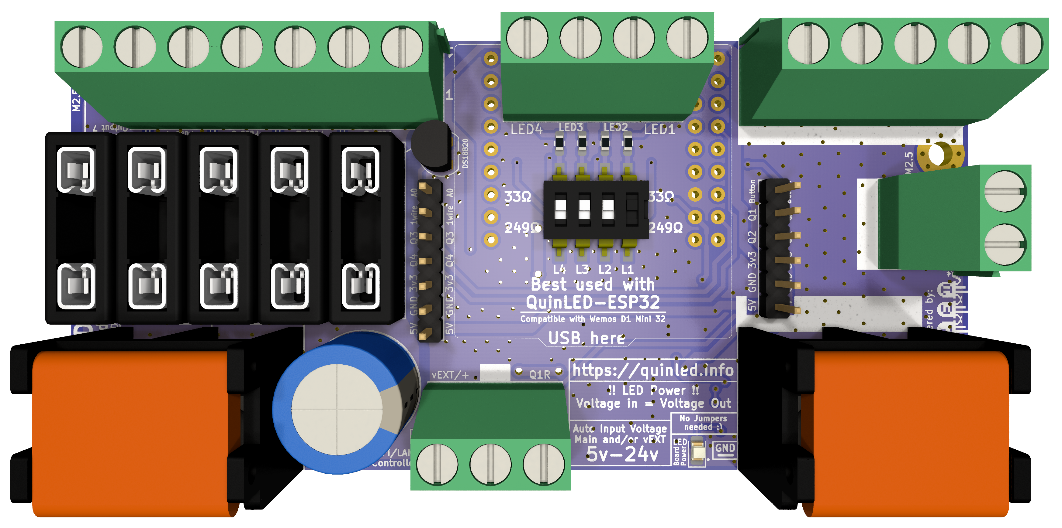 front
front 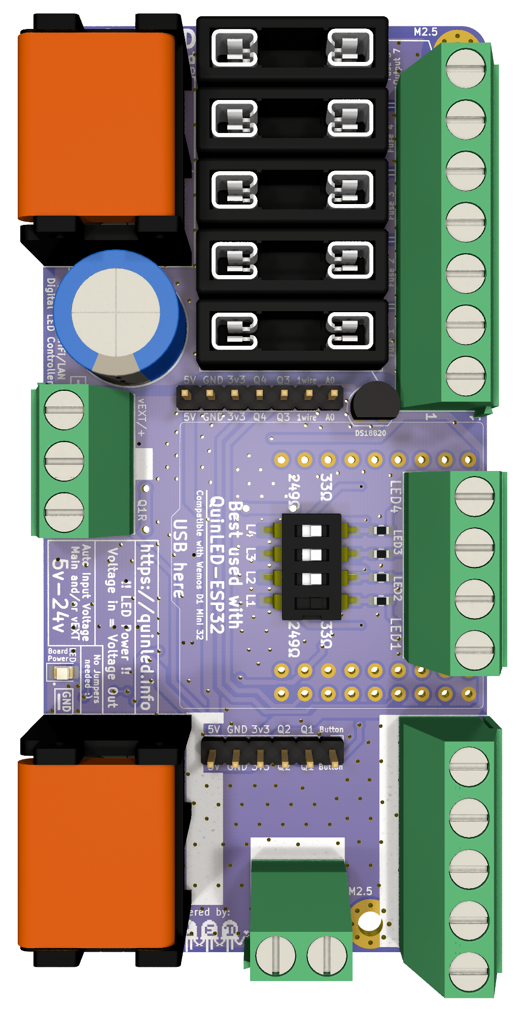 front veritacal (makes it easy to read pinout for dupont pins)
Wiring Guide
Wiring LED strip seems simple but becomes more complex the longer the length becomes. The QuinLED-Dig-Quad has been designed to try and make cabling easy for medium to larger installations. It does this by allowing you to run a pretty high amount of current through the board and having lots (7) positive and negative wiring points run through 5 independent fuses. This makes power injection for larger installations much easier, even if you are using just one data channel with an ESP8266 for instance.
The board is 5v, 12v and 24v compatible. Although this doesn’t make a difference in wiring it up it can make a difference in designing your LED install. Generally speaking 12v or 24v Digital LED strip can be run in longer lengths and with more LEDs without suffering as much voltage drop as their 5v counter parts but the downside is that these are generally per 3 or per 6 addressable instead of per 1 for 5v.
Make sure to also check out the following pages, QuinLED-Dig-Quad power limits. Also, make sure to check out the wire thickness needed page to determine what thickness cable you require for your desired lengths and application! Also remember to provide proper cooling for your LED strip although with Digital LED strip it is very dependent on what is going to be displayed, random color don’t generate too much heat but sustained white output will quickly burn up your LEDs!
Digital DATA Signal
Different from analog LED strips, digital LED strips have a positive and negative rail but also need a data signal (or sometimes a data and clocks signal) to work. While power can travel both ways (and is intended to be used that way with power injection), the data and clock signals can only follow the arrows on the strip and thus are uni-directional. You don’t have to worry about data or clock signals degrading on the LED strip itself because they are boosted by each LED (pixel/package) to the next one (max 1 meter). The data signal from the controller is much stronger and will generally be ok for 5m to 10m.
When soldering on your wires or applying the strip in it’s final destination, check that the arrow is pointing in the right direction!
Wiring Diagrams
For the suggested QuinLED-Dig-Quad wiring diagrams, please see here.