QuinLED-Dig-Quad DIY v3
Hardware guide
This hardware guide is for board revision DIY v3r2, please click here to see the previous DIY v2r6 version
This board is also available in pre-assembled form!
To build the QuinLED-Dig-Quad you are going to need several components which are listed below. As a little disclaimer, please take a look at this article about my shopping links. After reading that, make sure to also take a look at the additional hardware and tools you might need to be able to complete this project. Then I also have articles about 5v, 12v and 24v addressable LED strip and the differences of them and even an article about different addressable LEDs chips you can buy!
Those articles are a lot of information but will teach you everything you need to know! For lots more articles about LEDs and making a setup please see the addressable LEDs section or otherwise ask us on Discord!
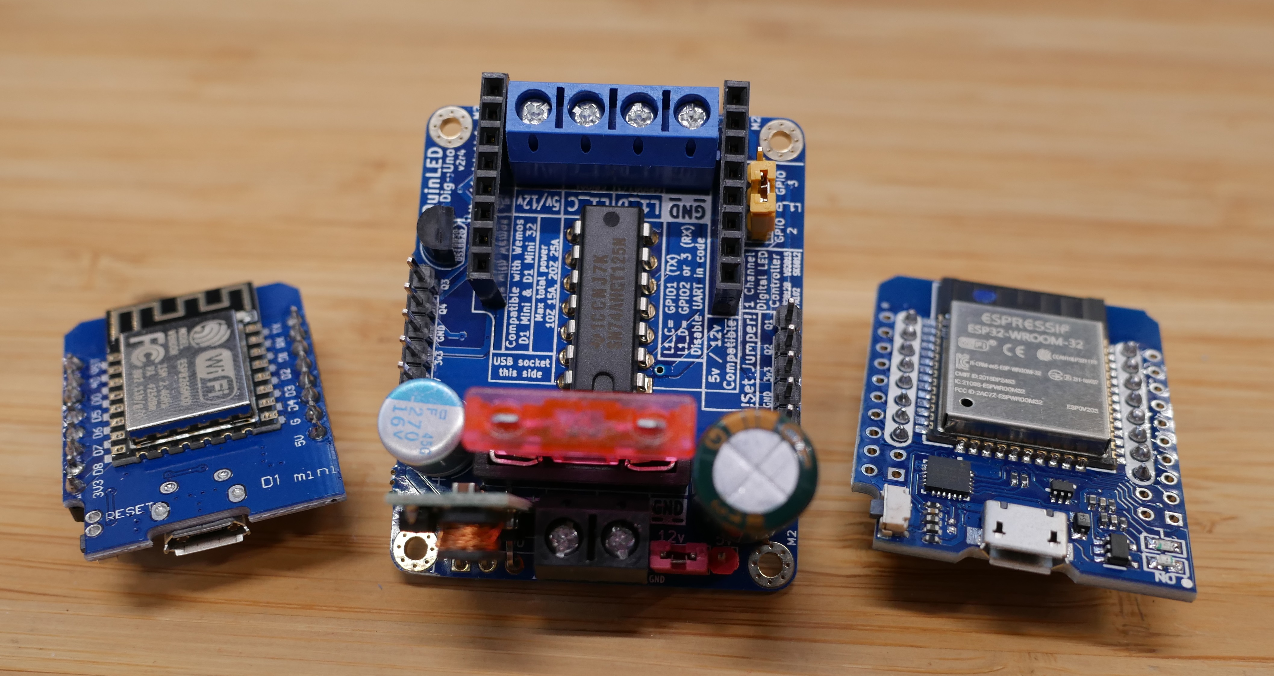
 Currently OLD photo!
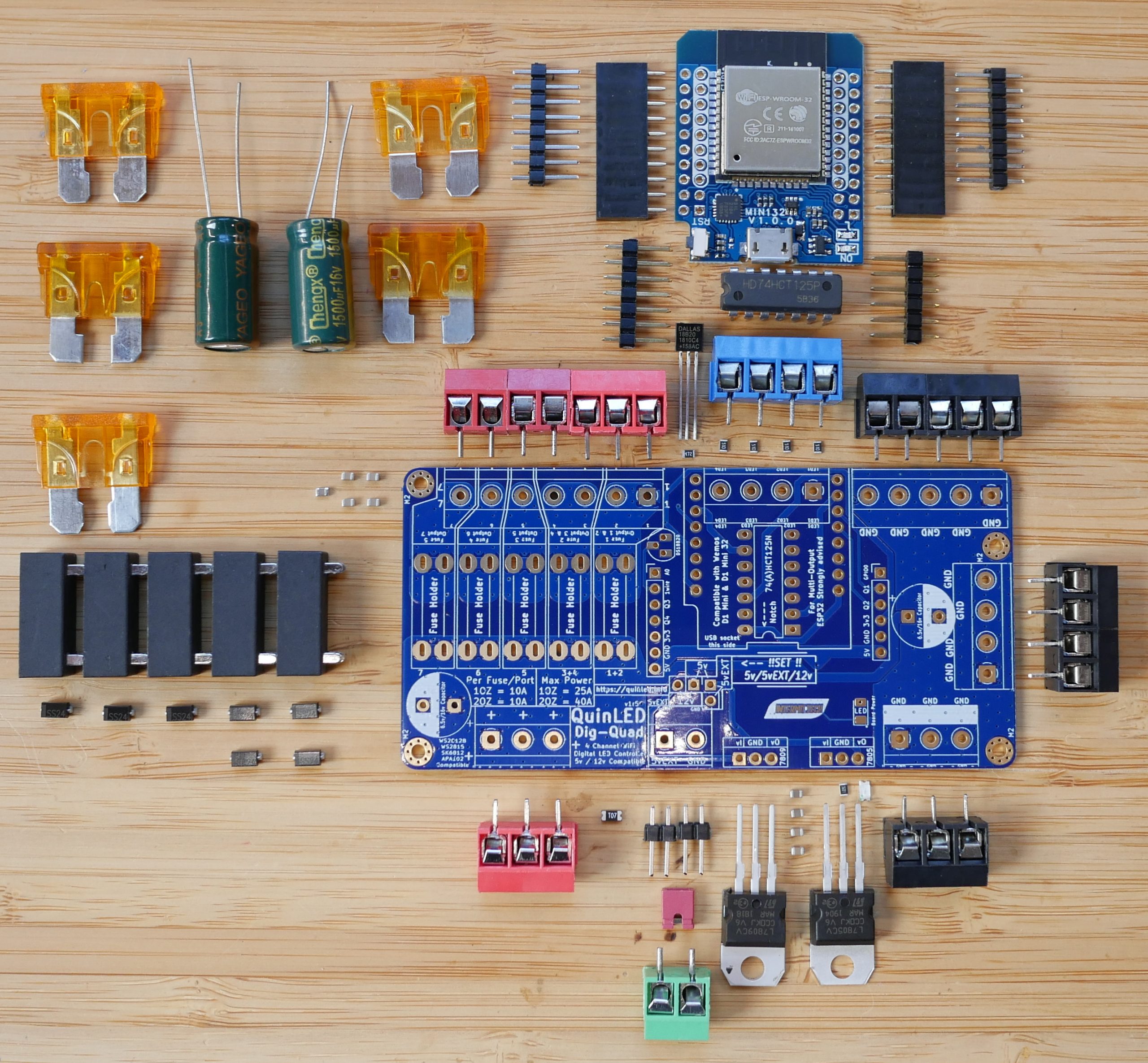
Total costs for a single board
What a single fully built QuinLED-Dig-Quad board will cost is a bit hard to determine because you have several options. Those options are to make the board only 5v compatible or 5v + 12v/24v (requires extra components). The second choice is if you are going to for a 1OZ copper board or 2OZ. (Please see specifications for power handling changes!)
These per board values are a bit skewed because it’s calculated using bulk bought components, buying minimum quantities of all the components will make it a bit more expensive per board
The base board with only 5v compatibility will cost you about 15$, adding 12v/24v compatibility to that will cost you an additional 3$. So that raises the total cost from 18$. Then you still need an ESP32 this will cost you about 6,5$ to 7$ on average.
So the cheapest would be a 5v only board with an ESP32 on it and that would cost you only ~24$. The other side of the spectrum is a 12v/24v compatible board with 2OZ copper and with an ESP32, this will set you back ~30$ per complete board.
This calculation doesn’t include shipping because that can vary greatly between where you are and where you buy your components.
Board Summary
You need the following components and quantities:
Components needed
Most components come in multiples of 5 or 10. I will try to link to several batch sizes available for more expensive components so you don’t immediately have to buy the amount for 10 or more boards. Of course, if you do, the per board the price becomes (much) cheaper! Also when buying larger amounts of components you slowly but surely amass common components used in hardware tinkering which are convenient to have lying around!
All amounts of the components will be listed in green text. The amount listed there is for building a single board!
![]()
QuinLED-Dig-Quad PCB boards
- 1x QuinLED-Dig-Quad PCB
Generally I order my PCBs from PCBway but I have also kept DirtyPCB as an option. You’ll have to look at both which can offer you the best price for the boards + shipping.
Slow shipping is SLOW (sometimes 8+ weeks). PCBway e-packet is often a good compromise between decent time and money
— If you do not have a PCBway account yet, consider creating one using this affiliate link! 🙂 After creating come back to this page and use order link above.
![]() PCBway – QuinLED-Dig-Quad DIY v3r2 PCB order link (preferred)
PCBway – QuinLED-Dig-Quad DIY v3r2 PCB order link (preferred)
![]() DirtyPCB not yet available
DirtyPCB not yet available
Ordering information
To order the boards you don’t need to fill in too much, please see the following sections for the board house you are going to use:
PCBway
PCBway generally sets all options correctly! You mostly need to select a color for the board and if you want 1OZ or 2OZ!
tip: Try selecting between 5 PCBs or 10PCBs, they often offer them for the same price!
DirtyPCB
Here you need to set the board size to 10x10cm, select a “protopack” and change the board thickness to 1.6mm. You can also select a color of the board if you want but this can influence cost.
Gerber files?
I do not release the gerber files directly. I have had bad experiences doing so in the past so will not be doing so. On the flip side please know that I continually try to update and improve the boards where I can! Using the links from PCBway and DirtyPCB also helps me do that, I hope you can understand.
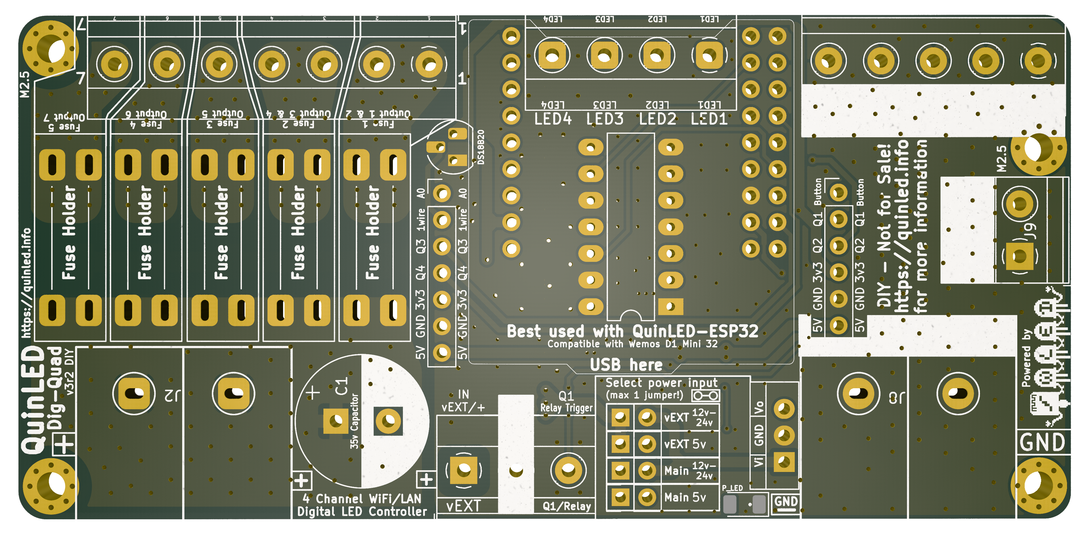
Board size (without ESP) is ~10cm by 5cm
![]()
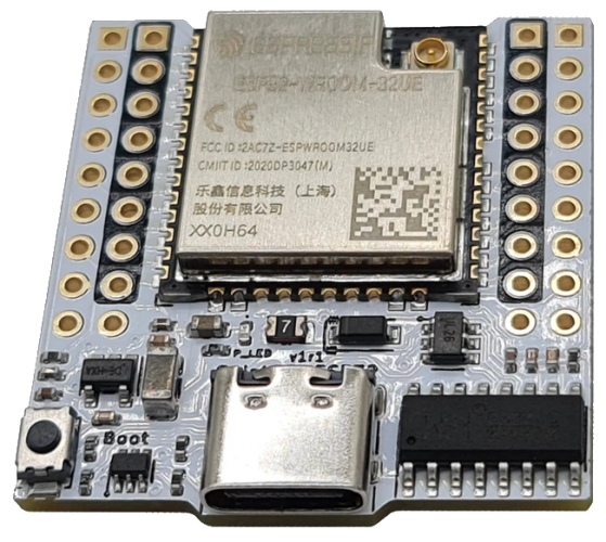
QuinLED-ESP32 or Generic Wemos D32 Mini (ESP32)
The main brains for the QuinLED-Dig-Uno is an ESP32! Because of quality issues when buying the generic modules in bulk I have developed my own version called the QuinLED-ESP32! Because this allows me to make more changes than what is available on the market there is a version with a board antenna (AB), external antenna (AE), extra options (AE+) and even an Ethernet version (ABE) so you can hard-wire your board to your local network. This helps especially when you are wanting to drive pixels in real-time using xLights and such.
The board is also still compatible with generic Wemos D32 Mini (ESP32) modules.
!When using the generic Mini32 ESP board, make sure the first row of front pins overhangs at the USB side. This is because a generic board is 4×10 pins but my modules are 4x 9 pins so on the generic boards the first row, starting at the USB plug are not used and should not be connected!
*These wemos boards are different then the MH-ET Live ESP32 I used in my Analog QuinLED-Quad and QuinLED-Deca board designs
- 1x QuinLED-ESP32 (any variant)
and / or
- 1x Wemos D32 Mini (ESP32)
![]()
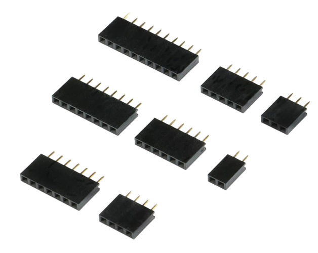
Female headers
For the board you need 2 types of female 2.54mm headers
- 1x 9 pins 2.54mm female header
- 1x 18 pins 2.54mm female header (dual rows of 9)
*If you cannot find dual row 9 pins you can also use 2x single row 9 pin with a bit of squeezing!
*If you cannot find 9 pins and/or 18 pins headers. You can also use 10 pins and 20 pins variants and have it overhang on the backside!
![]() 1x 9p/10p 2.54mm single row 2.54mm female header
1x 9p/10p 2.54mm single row 2.54mm female header
![]() 1x 18p/20p 2.54mm dual row 2.54mm female header
1x 18p/20p 2.54mm dual row 2.54mm female header
Screw terminals
To secure all the wires to the board you are going to need several screw terminals. I personally use different colors for input and output but buying multiple colors does make it more expensive (buying multiple colors gets you a lot of terminals in stock 😉 ).
- 2x Large 2p “HB9500M” 9.5mm terminals
- 1x 7p positive 5.08mm terminals
- 1x 5p negative 5.08mm terminals
- 1x 2p negative 5.08mm terminals
- 1x 3p vEXT input 5.08mm terminals
- 1x 4p LED data output 5.08mm terminals
As you’ll notice there are “odd” value numbers too like 5p and 7p. These can’t be made by just combining 2p connectors together (they slot into each other for larger numbers). You’ll have to combine 2p and 3p connectors to achieve 5p and 7p versions.

On the pre-assembled boards I use “color coded” terminals to identify which terminal is meant for what but on DIY boards this can increase cost significantly if you are only building a few boards. On those boards I use:
- Red for positive
- Black for negative
- Green for vEXT
- Blue for LED Data Channels
*If a seller has a “copper feet” and “iron feet” option please choose copper!
Large “HB9500M” power input terminals
![]() 5 Pcs 9.5mm HB9500(M) terminals
5 Pcs 9.5mm HB9500(M) terminals
Other terminals
![]() 20 Pcs 2 pin Blue/Green/Red/Black 5.08mm Screw Terminal (has all colors available!)
20 Pcs 2 pin Blue/Green/Red/Black 5.08mm Screw Terminal (has all colors available!)
![]()
20 Pcs 3 pin Blue/Green/Red/Black 5.08mm Screw Terminal (has all colors available!)

2.54mm Male pin headers
For the GPIO pins you need to get some pin male pin headers. The pins come on a strip and you can just buy a strip of 40 and just snip off the length you need for each section.
- 2x 4 pin single row 2.54mm male pin headers (Power Selection Pins)
- 1x 4p double-row will also fit!
- 1x 7 pin single row 2.54mm male pin headers (GPIO Pins)
- 1x 6 pin single row 2.54mm male pin headers (GPIO Pins)
- 1x 2.54mm Jumper for power pins
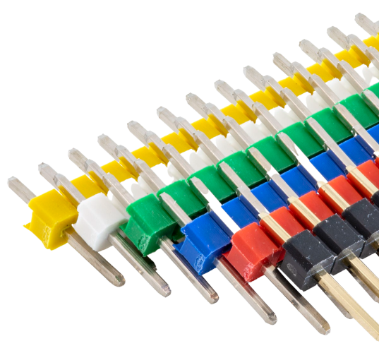
2.54mm pin headers (different colors) + Jumpers
If you’ve seen my example boards you probably noticed I make the power selection pins and jumper red. The reason I do this is because those determines the voltage the board runs at, setting it wrong can damage the onboard equipment so using a different color for it can help you to remind to check it!
I recommend getting a kit of colored pin headers + jumpers using the link below!
![]()
Set of Colored pin headers + Jumpers (Amazon link without jumpers!)
Jumpers
!If you bought the above pin header kit from Aliexpress, you do not need separate jumpers!
To be able to set the voltage of the board to 5v or 12v/24v you are going to need a little jumper. To make them standout I recommend getting a kit with several different colors. On my boards I use red for the voltage select.
*Aliexpress link is for extra long jumpers which are easier to use!
- 1x 2.54mm Extra Long Jumper (Red)
![]()

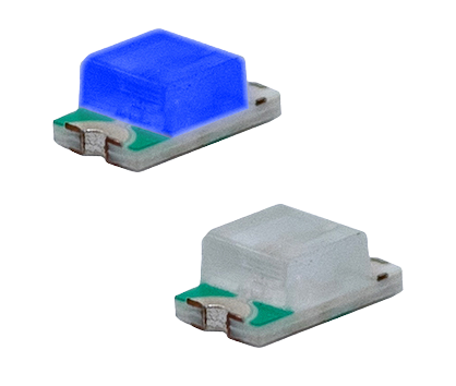
SMD LED
The board has a spot for a 1206 size LED, for the DIY boards I recommend using a 1206 size blue LED so that you can see when it’s on or off!
- 1x 1206 Blue LED
Capacitors
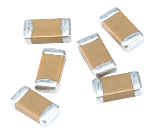
SMD Capacitors (1206 and 0805)
To stabilize power delivery to all components a few capacitors are needed. For space saving and ease of soldering we’re mostly using 0805 size capacitors with 2x 1206 size exceptions.
Required:
- 2x 0805 10v 0.1uF (100nF)
- C4, C5
- 2x 0805 10v 10uF
- C3, C6
Optional:
- 2x 1206 35v 1uF (Optional DC-DC converter input / output)
- C1, C2
- If not using 24v LEDs the capacitor doesn’t need to be 35v but can be 16v or 25v!
*You will need a tweezer to put these into place, make sure to check out the tools section!
0805 Capacitors
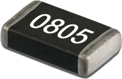
1206 Capacitors
(Optional Capacitor books)
Optionally you could also choose to buy an 1206 and/or 0805 capacitor book. This booklet comes with lots of different values included, check it out over here.
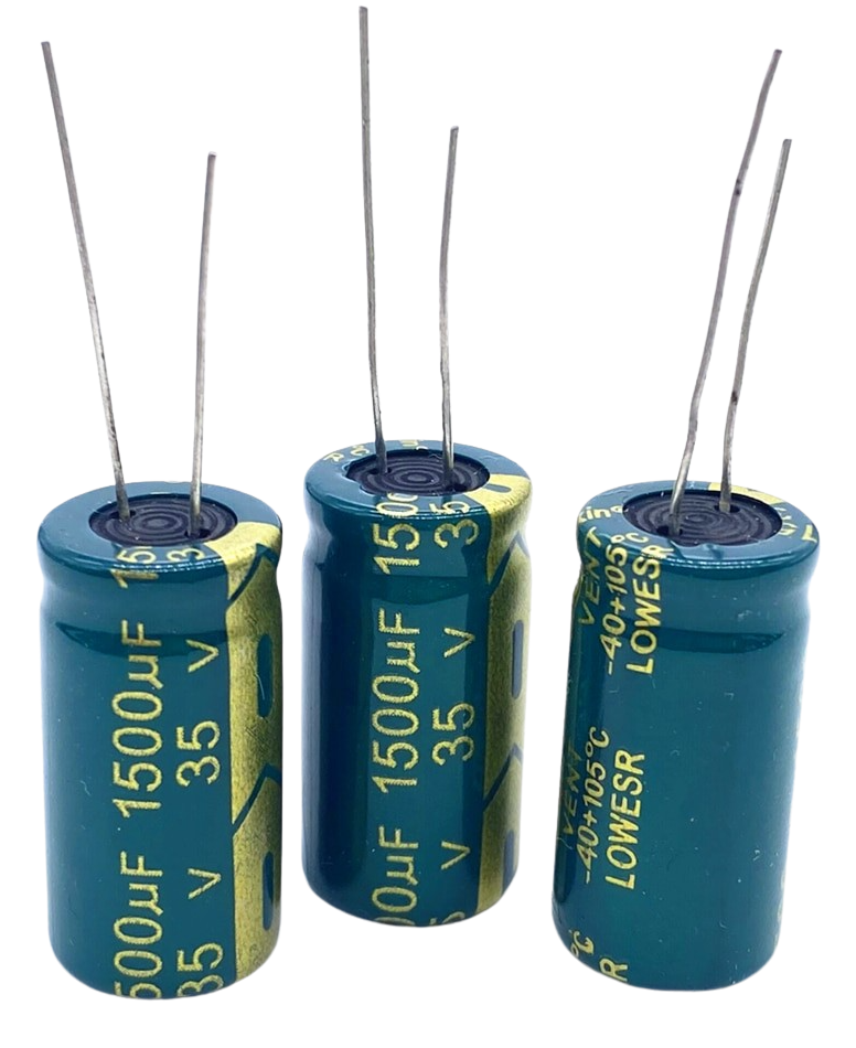
 Bulk through-hole capacitor
As a local power buffer and to also try and suck up possible over voltage conditions the board has 1 large bulk capacitor. To make sure this can handle up to 24v input power we nee a 10mm x 20mm size capacitor of at least 35v.
Required:
- 1x 12.5 x 20mm 35v 1500uF
- C5
- If not using 24v LEDs the capacitors don’t need to be 35v but can be 16v or 25v!
![]() 5 pcs 35v 1500uF 12.5 x 20mm (or higher) capacitor
5 pcs 35v 1500uF 12.5 x 20mm (or higher) capacitor
*On Aliexpress it’s hard to find 12.5mm variants but there are plenty of 13mm variants, ordered the version from the link to test fit!
SMD Resistors
The resistors needed to build the board vary by what features you want to use, please see them below and buy what is needed for the functions you wish to use!
- Required
- 1x 0805 4.7k Ohm resistor (For power LED)
- 4x 0805 33R or 249R Ohm resistor (For LED data lines)
- Optional
- 1x 0805 4.7k Ohm resistor (For Dallas Temperature Sensor)
- 1x 0805 10k Ohm resistor (For Button pin)
- 4x 0805 10k Ohm resistor (HW Pull-Up/Pulll-Down pads for Q1-Q4 GPIO pins) (Your application of Q1-Q4 might need them, or not!)
*You will need a tweezer to put these into place, make sure to check out the tools section!
![]() 100 Pcs 0805 Resistor (various values)
100 Pcs 0805 Resistor (various values)
(Optional 0805 Resistor book)
Optionally you could also choose to buy an 0805 resistor book. This booklet comes with lots of different values included, check it out over here.
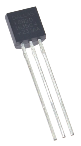
Dallas DS18B20 TO-92 Temperature sensor
The QuinLED-Dig-Uno has a spot for a Dallas DS18B20 TO-92 temperature sensor. It’s a cheap way to add a little sensor to the board!
- 1x Dallas DS18B20 TO-92 temperature sensor
Level Shifter
The ESP32 natively operates at 3.3v but the Digital Addressable LED strips expect 5v for their input logic signals. Often, sending 3.3v will work but if you start using longer cable runs or longer LED strips, errors can start to show up. Feeding a correct 5v data signal prevents these issues!
The variant used (74AHCT125N in a DIP14 package) is suited for high speed switching which is required for APA102 LED strip for instance. Both the LED1 and LED2 are fed through the level shifter! They are cheap if you buy them in packs of 10. The DIP14 package also means they can be easily soldered directly to the board or if you so desire can be placed into a socket.
*These shifters are uni-directional, you cannot connect switches or anything else that sends input or expects 2 way communication back to the board on these channels! The broken out Q1-Q4 GPIO pins on the board do not have this limitation.
- 1x 74AHCT125N DIP14 Level Shifter
![]() 74AHCT125N Level Shifter (Shopping links have different amounts!)
74AHCT125N Level Shifter (Shopping links have different amounts!)
(The Aliexpress link is for 20, if you need less take a look at the following mouser listing. If that also doesn’t work for you, you can also find them on Ebay)
–update 2019-12-26
Although the AHCT is better (it’s faster) if you can’t find it in stock or want to save a little bit of money the non-“a” version works well for ws2812b, sk6812 and the likes. If you want to run APA102 or similar LED strip I still advise to get the “A” version!

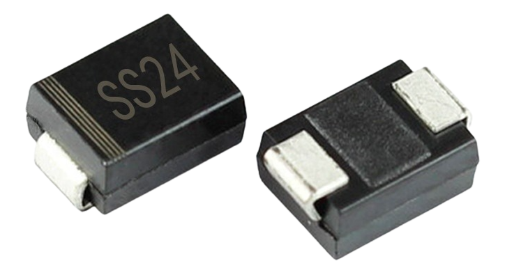
SMD Diodes
The QuinLED-Dig-Uno has several diodes on board. These serve 2 purposes, there is a diode in parallel with both the input terminals and the output terminals, combined with the fuse these should help in reverse polarity situations (it should blow the fuse before damaging onboard components).
These diodes are a lot bigger then on my previous boards to make soldering easier! Tweezers are still recommended though! I have also put little stripes on the board to highlight the orientation.
Do NOT connect both a power supply AND USB at the same time!
(That said, the QuinLED-ESP32 has protections for this so with those it is allowed)
In the current design the fuses blocks this, take the ESP module off for the initial flash, later flashing can be done while being inserted into the QuinLED-Dig-Uno using OTA methods
If you wish to use the USB-C port for real-time Ambilight effects like using Glow Worm Luciferin and you use a QuinLED-ESP32 using a micro/mini size fuse keeps the the USB-C exposed port for use!
- 6x SS24 diode
*You will need a tweezer to put these into place, make sure to check out the tools section!
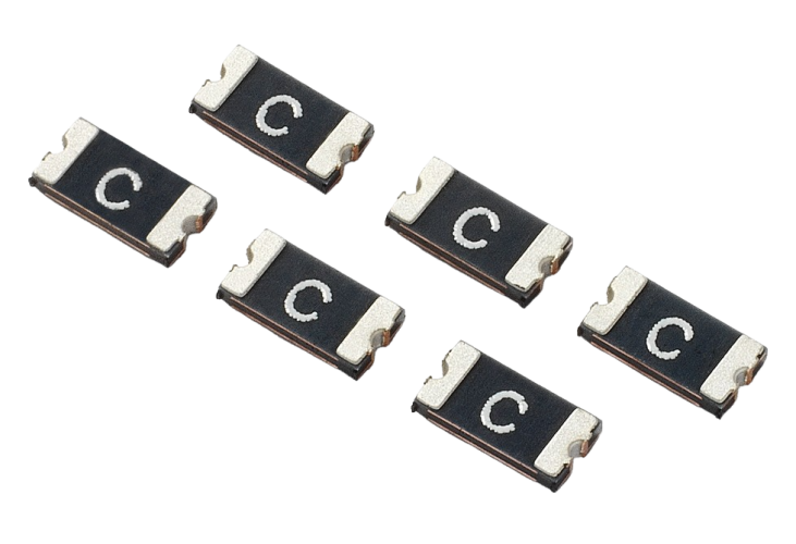
PTC Fuse (Auto Reset)
To protect the onboard electronics the board design incorporates a PTC “auto reset” fuse for the onboard electronics. In the case of something going wrong with the setup or electronics on the board it will limit current to prevent the electronics from breaking or in worst case causing a fire.
- 1x 1206 6v 750mA PTC
- 2x 1812 30v 1000mA PTC
![]()
*Needs to “kind of match” so 750-1100mA is fine and 30v-33v is fine too!
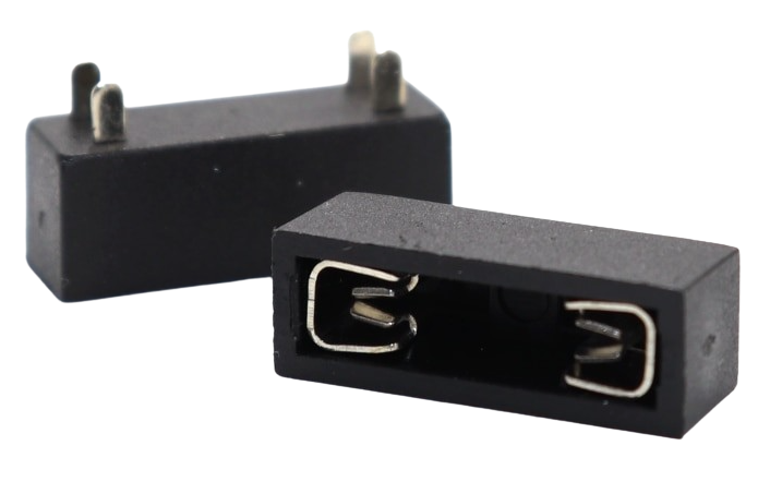
PCB Fuse holder
To add even more safety the QuinLED-Dig-Uno applies an inline fuse to all power running through it. In the case of a short or other over-current situation the fuse will pop and safely cut off power to the whole installation preventing any disastrous result such as a fire, etc.
The Dig-Uno is allowed to have a 10Amp fuse with 1OZ copper and max 15Amps with 2OZ copper but it’s recommended to size the fuse accordingly to your setup including wires and expected load!
- 5x PCB fuse holder
- 1x Assortment of ATO size fuses
(Thes PCB Fuse holders get a lot cheaper when buying in bulk, also check out this link)
Shipping can take very long for this item, you can also find them on Mouser or otherwise maybe Ebay. Or you can try searching for part nr: 3557-2
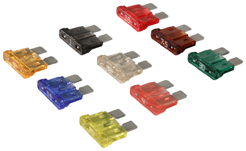
ATO fuses
Once you have fuse holders you will need some fuses. The fuse you’ll need will depend on your own setup but generally 5Amps, 10Amps and 15Amps are the most used values. With that said, to start out I recommend getting a assortment kit with lots of different values included.
![]() 1x ATO standard size fuse assortment kit
1x ATO standard size fuse assortment kit
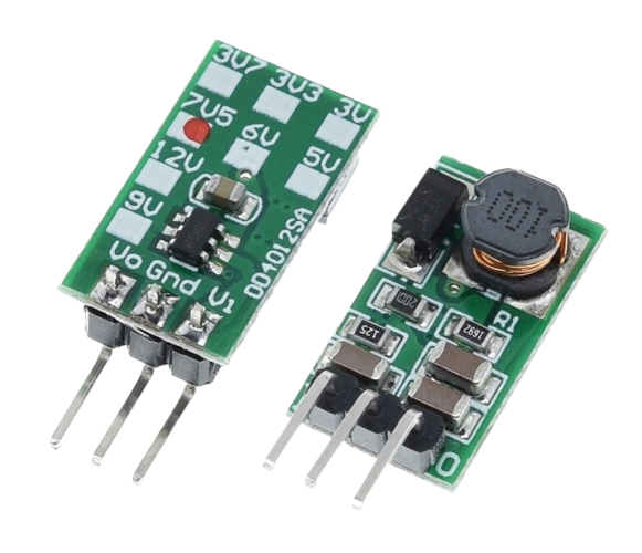
12-24v to 5v DC-DC converter
When putting together a 5v /12v-24v board you are going to need a DC-DC converter. This component is NOT needed if you are only going to run 5v. This DC-DC converter is tiny but it does a great job and doesn’t become hot! We are converting 24v or 12v to 5v for the onboard electronics. Linear regulators (such as the popular 7805) are not suited for converting 24v or even 12v to 5v for use with the ESP32 and other board electronics. The switching regulator used does this much more efficiently and thus with a lot less heat.
Sadly they this DC-DC converter is a bit more expensive than others models but nothing else worked in the current design or the board would have to become a lot bigger!
- Optional 12v only component!
- 1x DD4012SA_5v DC-DC Converter
![]() DD4012SA_5V 6v~40v to 5v converter (Get the 5v version, they are A LOT cheaper per 10)
DD4012SA_5V 6v~40v to 5v converter (Get the 5v version, they are A LOT cheaper per 10)
Get some LED strip and check out additional hardware components, tools and equipment
Above are all the components you need to assemble a complete QuinLED-Dig-Uno board! Again, often it’s best to order components for at least 5 boards, soldering doesn’t always go perfect and once you have one self-built Domotica device, it rarely stays at that number.
Also, don’t forget, this article only lists all the components you need, not the tools and other accessories you might also require. Make sure to take a scroll through this article to see what you might also need so you don’t get frustrated if you don’t have it while building or installing!
If you still need LED strip check out my article about which addressable LED strips to buy here.
And to power it all, check out this article about power supplies!