
Dig-Next-2
Status LED Guide
The Dig-Next-2 is fitted with various status LEDs regarding the power input, output and status of the built-in fuses. Below is an overview of these LEDs and their various states, because of how the LEDs work sometimes the “broken fuse” LEDs can be lit while they are not really broken, please read this article to find out the information about that!
Power input & generation
The Dig-Next-2 supports 2 power inputs:
- Main power in
- Supports auto True 5V-48V
- USB-C in
- Supports 5V only
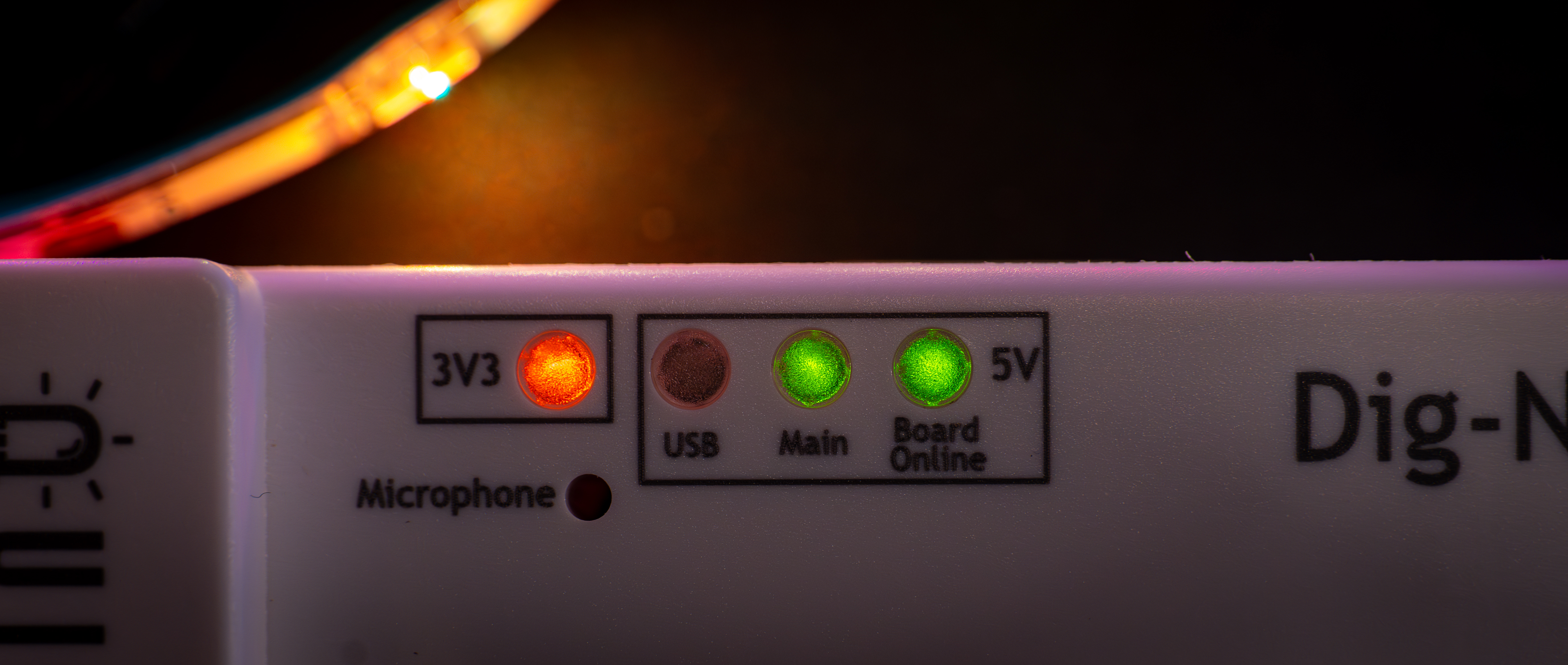
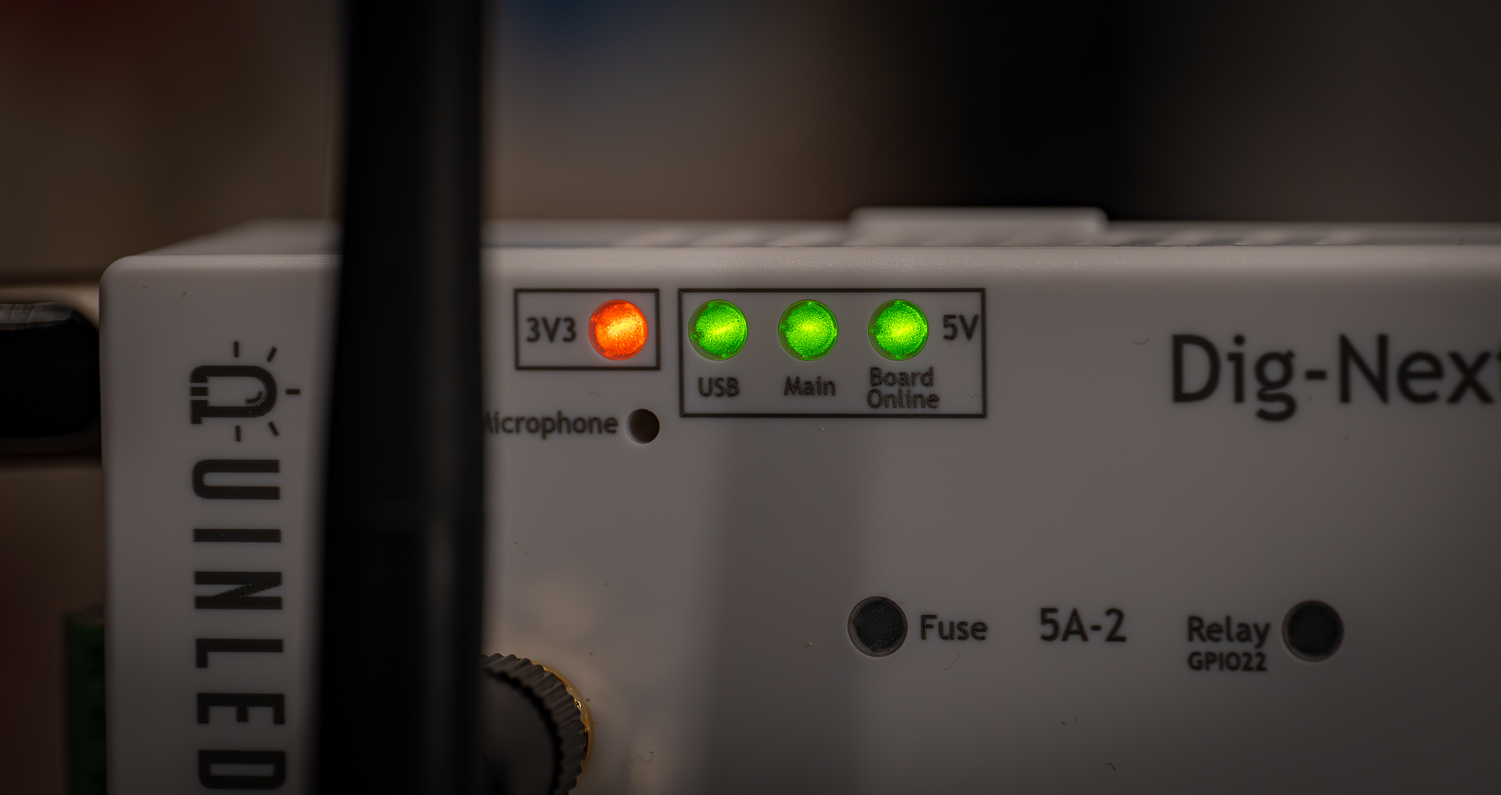
These can be used at the same time as explained in the dual power input feature guide. The indicators show which power is connected (Main, USB or both) and then that 5V output the onboard electronics is active with the board online LED. There is also a 3V3 LED light indicating that 3.3V is also being generated (the ESP32 runs from this). These LEDs are easy to get a quick glance if the board is online and what power sources are connected and working!
Everything 5V lights up green and 3.3V is Orange!
AC Relay
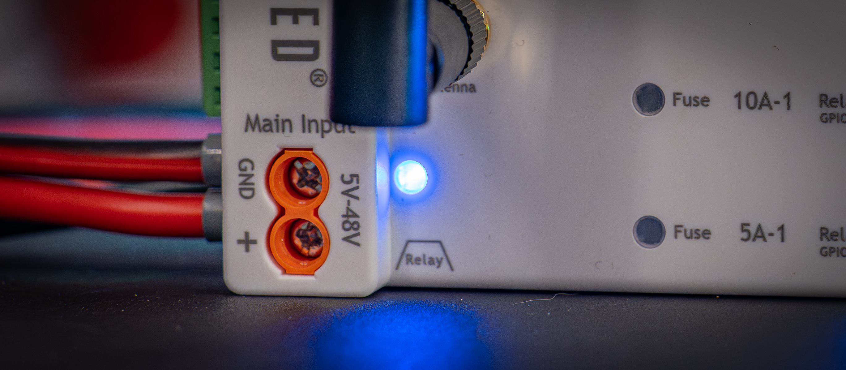
The relay port has it’s own dedicated output blue LED, this will light up when it’s providing 5V on the switched relay trigger (yellow) cable.
DC Relay outputs
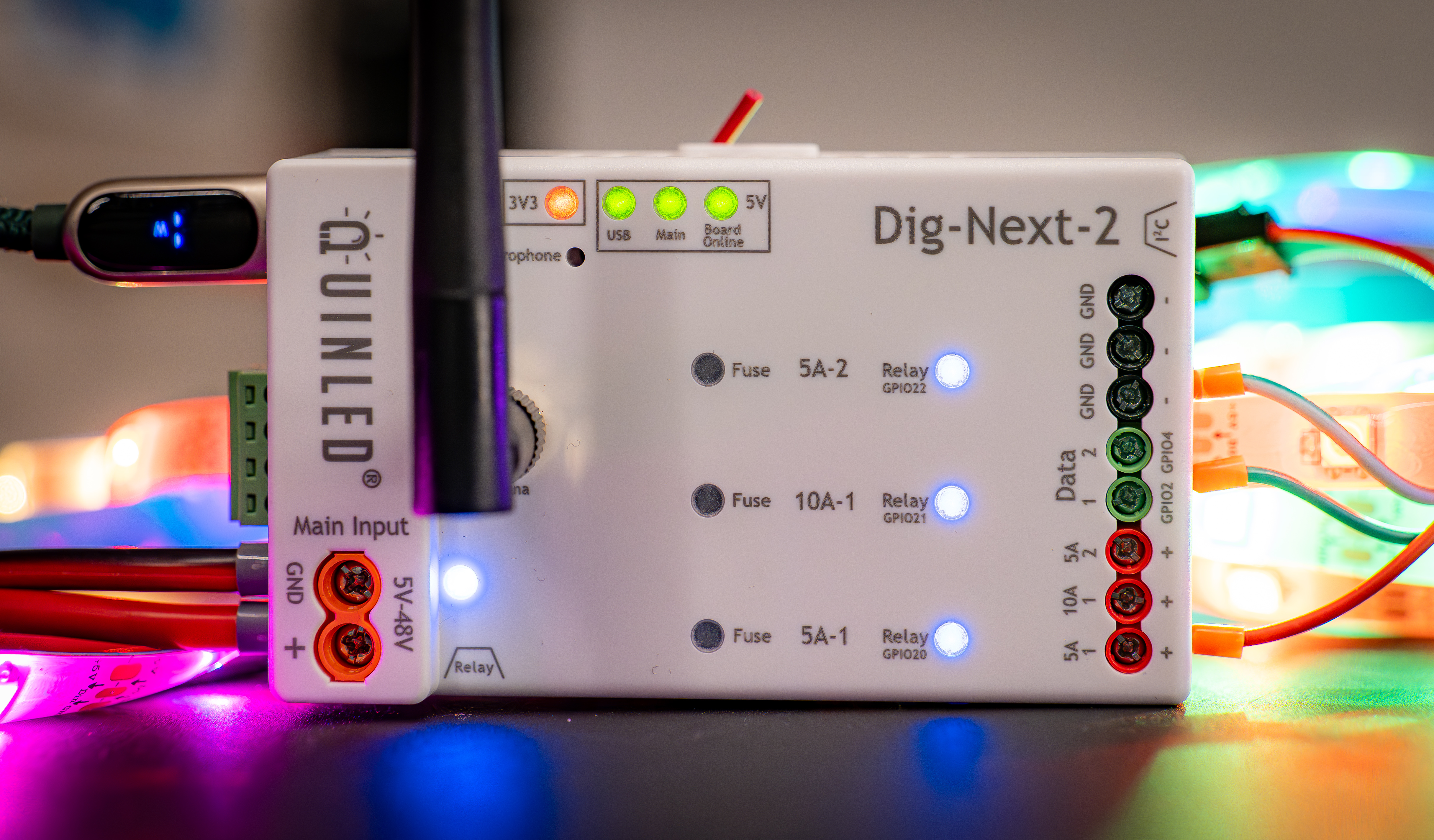
The Dig-Next-2 has 3 separate power outputs which also each have their own output enabled blue LED. If these LEDs are off, there is no power passing through to the output terminals! Please see the multi-relay guide on how to configure this.
Broken fuse indicators
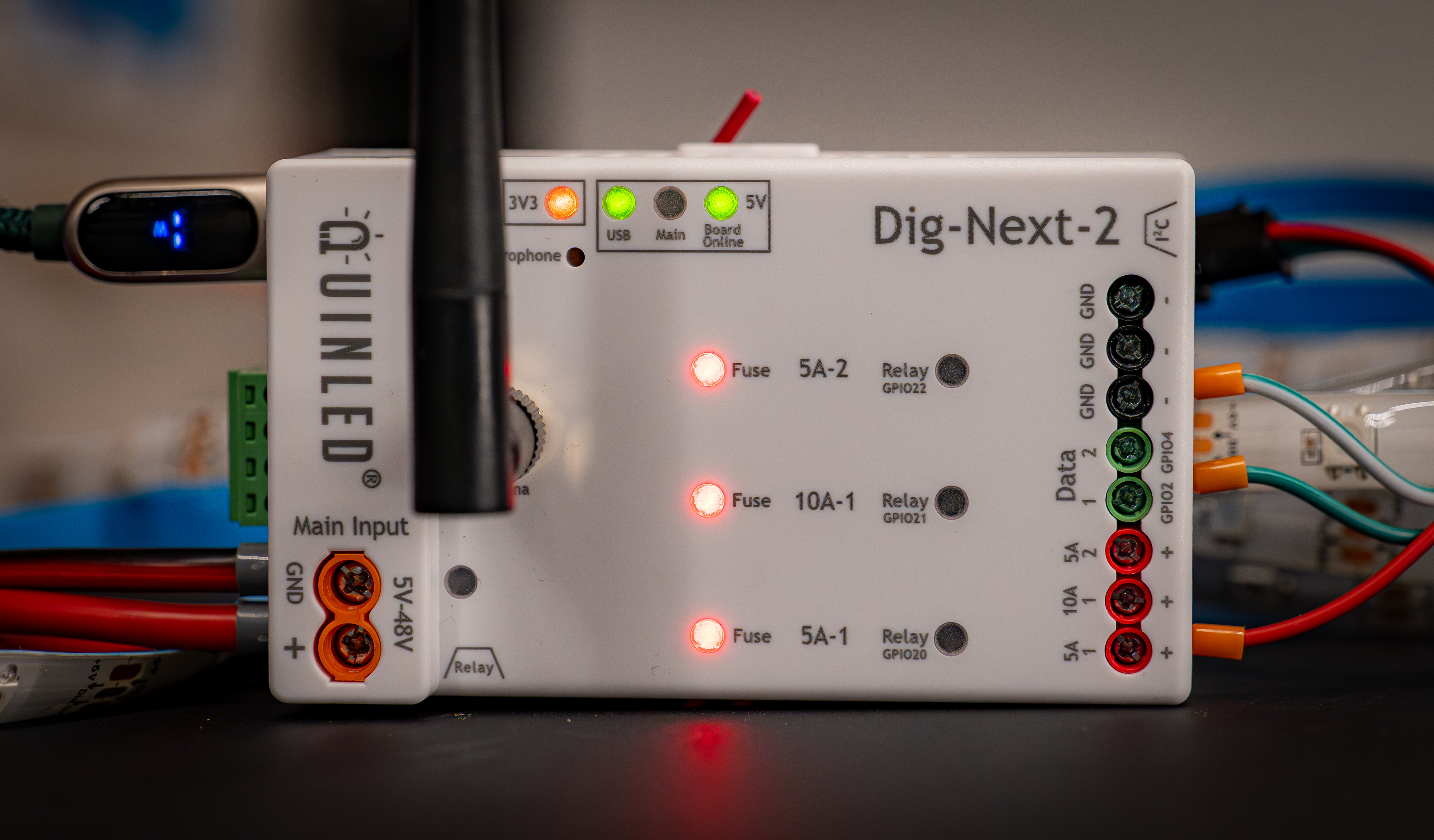
There are also 3x red broken fuse indicators on the board which will light up when a fuse has popped!
The circuit however also lights up in some other conditions which will be listed below!
Other conditions
The broken fuse indicators can light up or even pulse in some situations.
- Broken fuse indicators are all lit up when only USB-C is active
- When only USB-C is active and there is no main power supply attached but the outputs are “on” and thus the relays are enabled, the broken fuse indicators will all light up. With the current circuit there sadly is not a way to prevent this.
- You will probably only see this while programming the board, in normal scenarios it won’t occur!
- In the scenario where you have USB-C attached and have an AC relay on the main input, the DC relays are also disabled so this doesn’t occur!
- You will probably only see this while programming the board, in normal scenarios it won’t occur!
- When only USB-C is active and there is no main power supply attached but the outputs are “on” and thus the relays are enabled, the broken fuse indicators will all light up. With the current circuit there sadly is not a way to prevent this.
- All the broken fuse indicators are pulsing!
- This can happen when there is no programming on the board or during programming. It’s not harmful to the board and will resolve itself once the software is running.
- The broken fuse indicators glow faintly
- This can happen when WLED is turned off and the DC relays are turned off and there is no main power supply connected. With a main power supply connected, even if it’s off this glow most likely will not appear (depends on the power supply).
- The blue DC relay LEDs stay on a little while after turning off power in WLED
- This is correct behaviour, the Dig-Next-2 has an individual large capacitor per power output for power stabilization and the power in this capacitor needs to “bleed off” when the DC relay is disabled. If there is something attached to that power port it will go very quickly but on an empty port it can take 5 to 10 seconds.
Is there a way to disable the LEDs?
Sadly no, if the LEDs are too bright or you don’t want them at all my best advice would be to take some black electrical tape and block them on top of the controller. All LEDs are completely flush mounted so applying tape on top of them will sit nice and flush.