QuinLED dig2analog+ Wiring Guide
This guide is an (slightly updated) copy from the dig2analog (non-plus) article and images have not been changed!
Wiring between dig2analog and dig2analog+ is 100% identical
Hooking up the dig2analog+ is fairly simple since the board basically behaves like a single addressable LED or pixel thus you also hook it up this way. On the right or left side of the board (make sure to flip the switch to the incoming data side) you then hook up your RGB, RGBW or RGBCCT Analog strip and the board will convert the incoming data digital data signal to a PWM output to control the Dumb/Analog LED strip!
The board has input and output terminals for power and the digital signal at the top and bottom of the board. These can be used to daisy chain multiple boards as desired (recommended up to about 400 max per data channel on the Dig-Uno/Quad/Octa).
Here is a schematic drawing of a simple application of the boards:
Differences because it’s dig2analog+
1. Up to RGBCCT
2. Up to 6.3A per dig2analog+ board
 *correction, 3x dig2analog!
Analog/Dumb LED strip connection terminals
There are 5 negative outputs for RGBCCT and one fused positive. Strips (and power supply) supported is 12v – 48v! Please see the below photo which shows a zoomed in shot of the connection terminals for the Analog/Dumb LED strip.
[photo of board top shot]
Output channel power and fusing
The dig2analog+ has 2 “size” output channels. For the RGB channels each channel can do a maximum of 3A. The 2 white channels however have been upgraded to support a higher current up to 5A! This allows to use higher power Analog strip, specifically white strip such as 19.2w/m or 28.8w/m (although the full 5m would exceed the official rating slightly, in practice because of slight voltage drop and the white channels being beefy enough it should work fine).
Please keep in mind the total power for the board is still dictated by the fuse which is 6.3A! The max recommended fuse is 6.3A but lower value fuses are supported and encouraged. If your project is only going to be using 1A or 2A, it’s recommended to downsize the fuse to these values too! You can find the type of fuse easily online with this article.
Adding power injection
When you are chaining lots of boards at some point you will have to start adding power injection. The standard rules for LED strip don’t apply here and a chain of dig2analog+ can draw much more then 4A from a single edge injection but it will depend on what diameter wires you are connecting between the Dig-Quad to the dig2analog+ and daisy chained boards. The boards themselves have very little resistance and thus almost don’t drop any voltage. Each board can use up to a maximum of 6.3Amps but might use less then that depending on effect, patterns and such being displayed.
It’s recommended to use a Dig-Uno/Quad/Octa with a 10A fuse to feed the first dig2analog board. If your chain of boards requires more power I’d run a injection wire (the board terminals accepts up to 14AWG with wire ferrules) to the board furthest from the first board receiving power and injecting power there to equalize the voltages over the whole chain. This power injection needs to come from the same power supply and distribution & fusing board (such as the Dig-Quad) as the original power provider, running 2 separate power supplies is possible but requires a split of the positive path between 2 boards!
In practice I’d use a multi-meter after chaining several boards and see what the voltage sags to on the last board during normal usage, if voltage sags more then 10% to 20% (10% @ 24v this is about 2.4v drop) this will become noticeable and I’d suggest adding an injection wire like below.
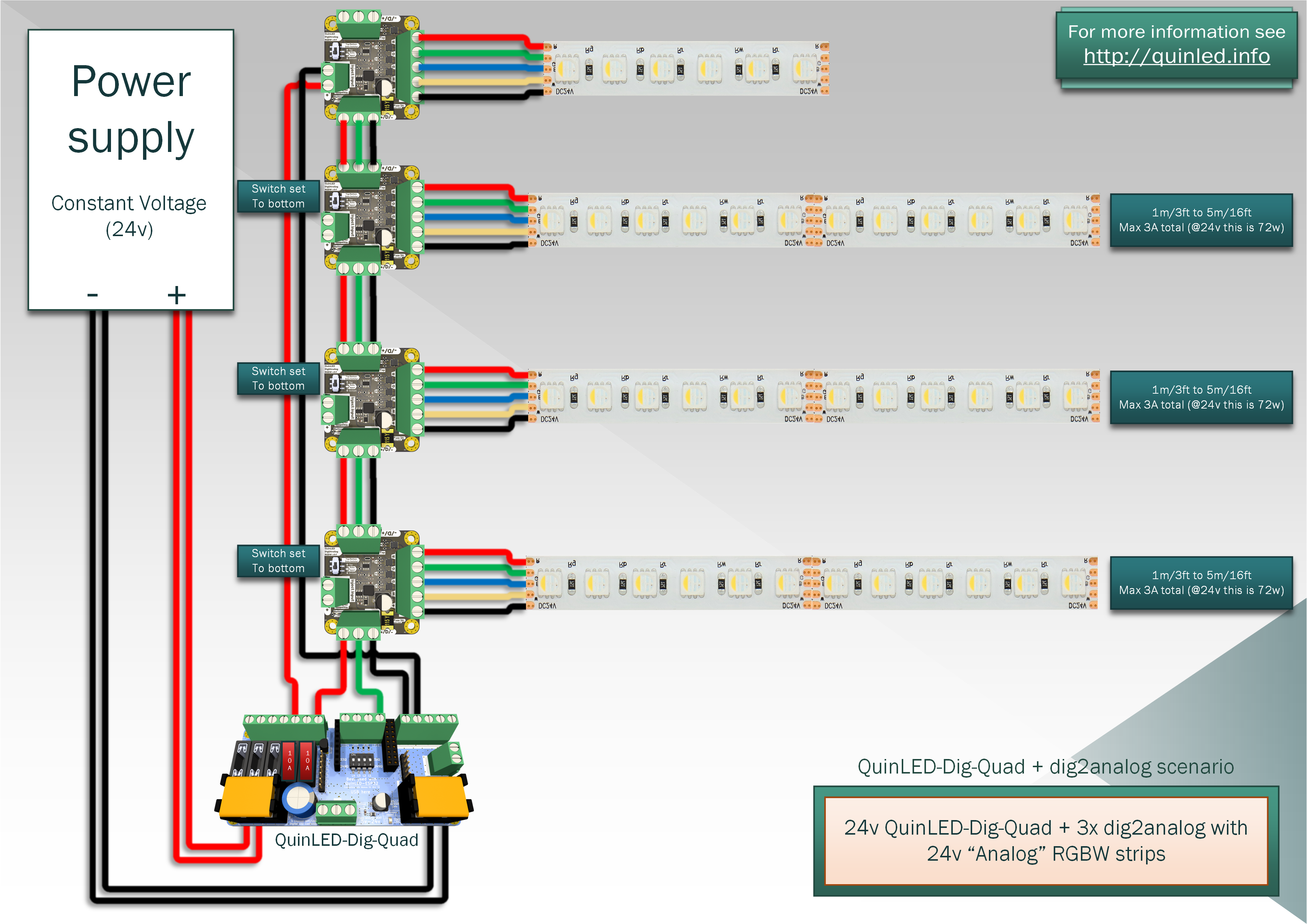 *scenario with 4x dig2analog(+)
Using 2 different power supply voltages
Sometimes you might want to run 5v addressable LEDs and 24v analog strips to add some white. While you can work with buck-converters (getting a 24v supply and then converting it down to 5v for the addressable strip) you can also use 2 power supplies if so desired, especially if the strips are going to be in 2 physically different locations this can sometimes be preferred.
*Running 2-wire (linked or twisted) cable for data+GND (in 33R mode on the Dig-Quad) is the preferred method for transporting the data from the controller to the dig2analog+ to make sure data arrives intact, even over longer distances.
Below schematic shows you how to connect a Dig-Quad running 5v for normal ws2812b addressable LED strips but using some extra 24v RGBW strip through a dig2analog+ to go along with it!
*The below diagram does not have a fuse for the 24v power supply, if this is a 5A or lower power supply, it likely isn’t required since it should shut off before burning your wires. If this is a higher current power supply it’s recommended to add appropriate fuses for the wires diameter used! Please also see the fusing part below.

Fuses and their placement
The dig2analog system is designed to work in conjunction with a Dig-Uno/Quad/Octa board for 2 reasons.
First these boards provide the proper 5v data signal that the dig2analog requires (3.3v data signal has not been tested!) but second these boards provide the fuses for the main power busses.
Yes the dig2analog+ contains a 6.3Amp fuse but these are connected only to the onboard electronics (with an extra fuse) and the positive output of the Dumb/Analog LED strip not on the power input side of the board, this task is left to whatever is providing the power. In the case of the Dig-Quad as shown above, this has 5 fuse positions and supports up to 10A max per fuse/output with a recommended total continuous current of 30A.
Thus your power distribution board is in charge of fusing that side of the board and wiring and the dig2analog+ will fuse it’s onboard electronics (it has a separate auto reset fuse for this!) and whatever is connected behind it (with the replaceable fuse). Please make sure to fuse appropriate for the used wire diameter or the expected load (whichever is lower).
Maximum distance between boards
The boards have been tested with up to 10m/32ft of 18AWG 2-wire cable with Data+GND on there between boards and this functioned perfectly during testing setups. (3-wire cable with Positive+Data+GND can also be used with the same expected results!)
In reality distance will vary depending on potential data signal outside interference and corruption. But in general it can be assumed that up to 5m/16ft will work reliable and up to 10m/32ft will also work well generally.
Power wise you will have to do your own calculations to see if you won’t get too much voltage drop with the diameter of cable you are using. The board terminals will accept up to 14AWG/2mm2 wires with ferrules!