QuinLED dig2analog+ specifications
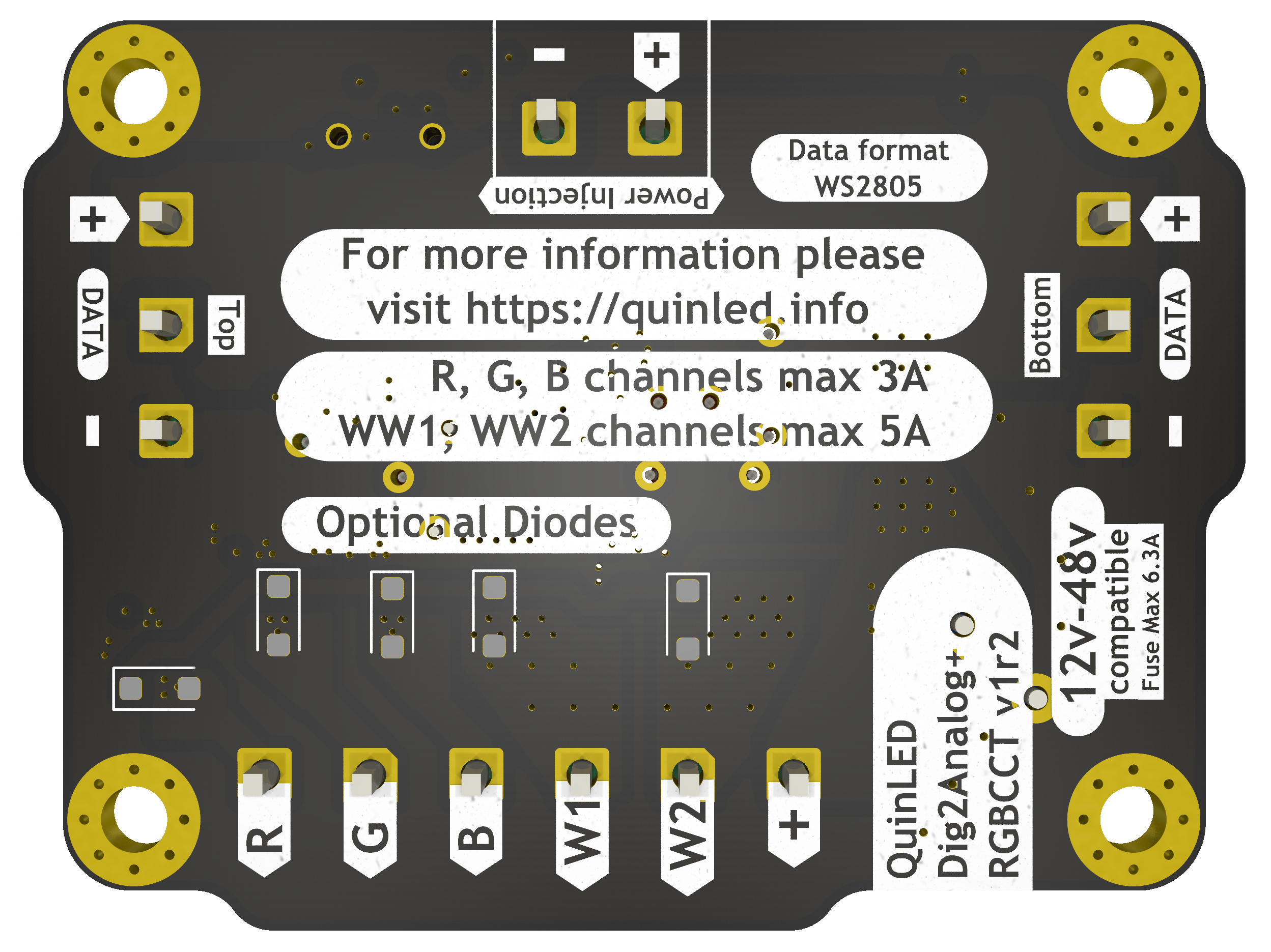
The dig2analog+ is based on the WorldSemi WS2805 chip. This chip is used to “extract” the data for a single LED/Pixel and the board converts it to a PWM output able to drive 12v – 48v LED strips up to RGBCCT (RGB + Dual White).
The onboard circuitry has been carefully tuned to be both efficient and have great performance. Other similar type boards use cheap/simple circuits but the result is often sub-par in regards to high idle power usage, driving capability, board temperature or have inverted control logic.
The dig2analog+ uses a fully custom DC buck converter setup to eliminate idle usage together with carefully tuned resistor values enabling both very low PWM levels as well as a correct full 100% (no PWM) output at the high end. The special “dual” MOSFETs on the board auto invert the signal in hardware so you don’t have to worry about this in software and sending 0 is off, and 255 is full on.
Features
- Uses newest WorldSemi WS2805 chip
- Up to 5 channels output
- Up to RGBCCT (Red, Green, Blue, Warm White, Cold White)
- 3x 3A “RGB” channels
- 2x 5A “White” channels
- 4kHz PWM frequency
- ws28xx protocol compatible
- Coupled with 33R output resistor
- Allows up to 10m* distance between dig2analog boards
- *Depends on specific setup and possible outside interference!
- Best suited for 2-wire (Data+GND) or 3-wire (Positive+Data+GND) cable
- Allows up to 10m* distance between dig2analog boards
- Up to 5 channels output
- 12v – 48v compatible
- Fused Output to LED strip with 6.3A replaceable fuse
- This is also the maximum recommended board power
- Replacing the fuse with a lower value fuse is fine and recommended if your setup/situation calls for it!
- If you are only going to be running 1A or 2A max, best to use a fuse of that size
- Fused Output to LED strip with 6.3A replaceable fuse
- “Link through” and separate Power injection terminals available
- Easy to daisy chain boards and feed in power into the chain where needed with extra injection wires
- Up to 15A current input/throughput with very low resistance for daisy chaining boards and power distribution
- Feed in connectors are *not* fused, recommended to have your power source fused
- Such as running the power and data through a Dig-Quad or Dig-Octa Brainboard + Powerboard.
- Chainable up to max 400 per “data channel” recommended
- That’s 2000 analog channels!
- Uses special “dual” N-channel MOSFETs
- No reversed/inverted data signal needed in software!
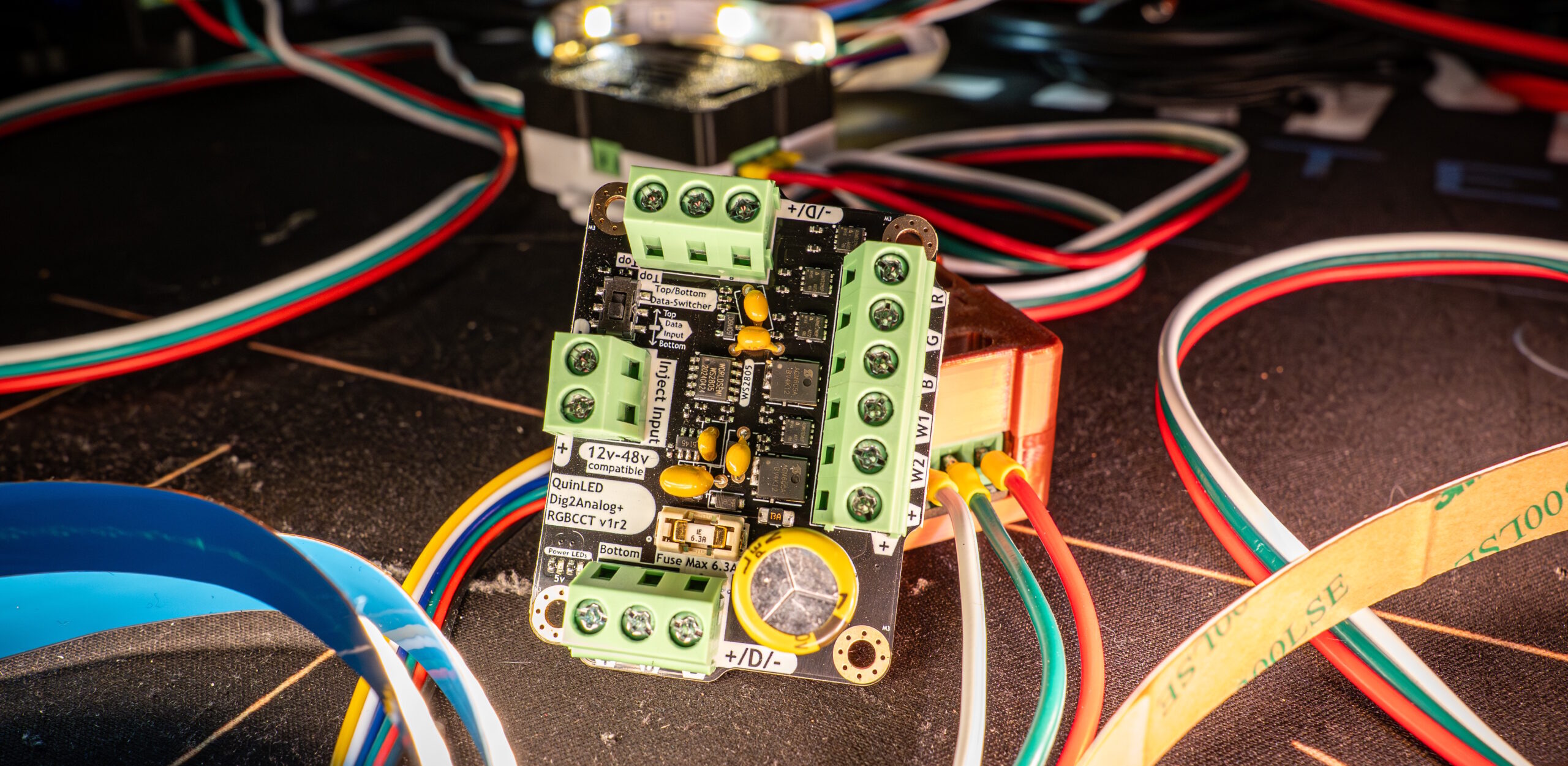
- Data input side switcher
- Allows you to change data in/out between top or bottom 3p terminals allowing the dig2analog to be used whatever orientation works best for your setup
- Set the switch to the side that will receive the data
- Allows you to change data in/out between top or bottom 3p terminals allowing the dig2analog to be used whatever orientation works best for your setup
- 4x M3 size screw holes to mount the board
- 3D printable enclosure available!
Screw Terminals
All screw terminals can accept up to 14AWG wire with a wire ferrule.
- 2x 3p 5.08mm for Positive – Data – GND
- Main input/output
- 1x 2p 5.08mm for Positive – GND
- Power injection
- 1x 5p 5.08mm for R+G+B+W1+W2+VCC_F
- Negative LED output channels
- VCC_F = VCC positive fused output