QuinLED Diff-Adv System guide
Back to QuinLED Diff-Adv main page
The QuinLED Diff-Adv system has been designed around the need to get LED data signals further then what the normal boards (like a Dig-Uno, Dig-Quad or Dig-Octa System) can provide. Where those boards mostly top out around 10m/32ft of data wire distance the QuinLED Diff-Adv system can get the same signals up to 500m/1800ft!
Just like the QuinLED Diff-Solo the Diff-Adv system consists of Sender and Receiver boards. The sender board takes in the LED data signals and transforms these single ended signals to a differential signal which it then outputs onto a standard UTP (CAT5E, CAT6, etc.) cable.
The receiver boards do just the reverse, they take in this differential signal and transform it back into a normal LED data signal to drive you LED strips and strings. The receiver boards incorporate everything you need for this such as power distribution, fusing, level-shifter, LED data output resistor, etc..
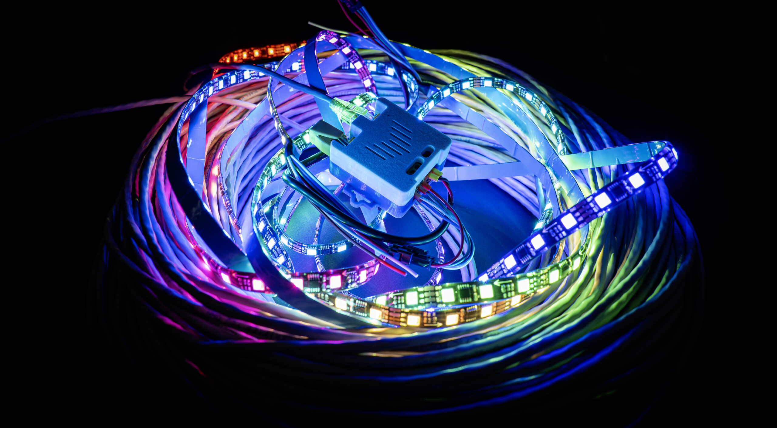
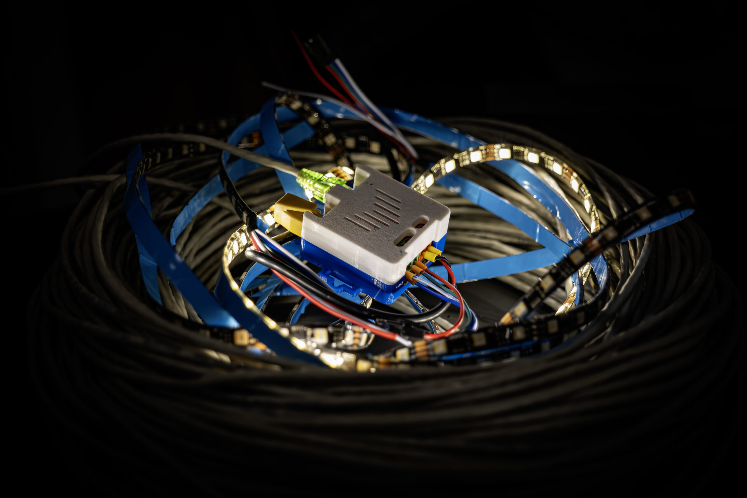 Receiver-Midpoint-1 running after 100m of UTP cable
Daisy chain System
The Diff-Adv system has been designed around the ability to daisy chain boards. The reasoning behind this is although you can get 4 LED data signals onto a single cable, most often you don’t need those 4 signals at the same spot. Thus instead of having a single receiver board with 4 outputs the system consists of 2 types of receiver boards called the Receiver-Midpoint-1 and Receiver-Midpoint-2.
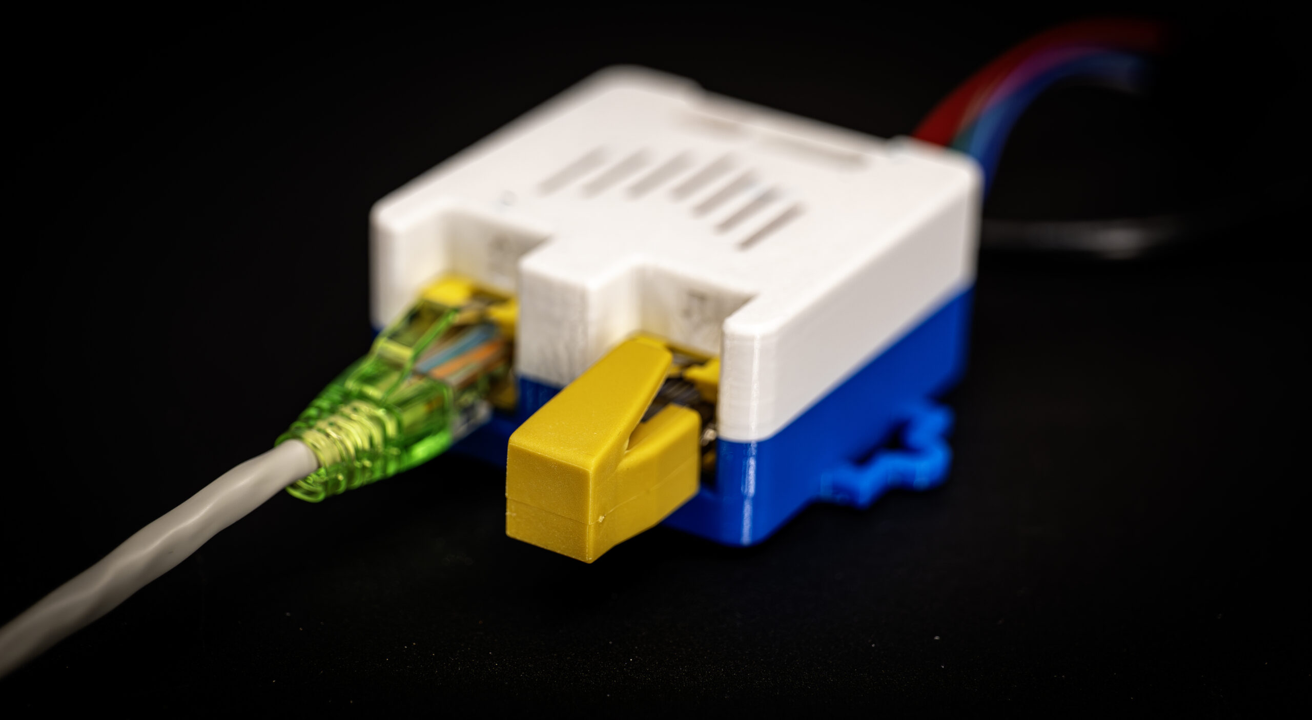
Again, such as the name implies these Receiver-Midpoint boards are not an endpoint for the system (if you don’t want it to be). Each of the Receiver-Midpoint boards feature a RJ45 socket for input and output of the signal. With this you can relay the 4x differential signal to a next board in the chain, this is done passively so even if one of the Receiver-Midpoint boards does not have it’s power turned on, the signal will still continue.
Pair 1-4 data extract switches
Each of the Receiver-Midpoint boards has 4x SMD switches on them, these switches direct which data pair you wish to select on the LED data output of that board. The order of boards does not matter for this. If you wish to extract Pair-3 on the first board in the chain and Pair-1 on the 3rd board in the chain, that’s perfectly fine.
It gets more advanced even, if you wish to extract Pair-1 on board 1 and board 3 in the chain, that’s also possible and fine. This will make the LEDs connected to those Receiver-Midpoint boards act 100% the same!
Terminator plug required
To make the whole system work you need to insert a termination RJ45 plug at the end of the chain. With each Diff-Adv Sender-4 you get a terminator plug included!
Example setup
Let’s say you have a QuinLED Dig-Octa and you use 4 of it’s 8 channels to feed LED data into the Diff-Adv Sender-4.
You have 2 rooflines you wish to add LEDs to but you are using high density LEDs and thus require 2 data channels for each roofline. For one roofline you need these spread far apart and for the other one you can have a single board that does both.
You’d run the UTP cable from the Sender-4 to the first stop where you have a Receiver-Midpoint-1. Then from that board you use a new UTP cable that goes to the second spot where you need data. And then from that spot you’d run a third UTP cable to the next spot where you want the data to go. At the last board, you insert the terminator into the output RJ45 socket.
Ideally using a chain as such is less wiring then going to each point directly (this is also possible of course but very much depends on your layout).
More advanced usage
Let’s say you have lots of LEDs you are driving all located in the field with boxes that have their own power supply and you’d like to ability to cut off this idle usage during the day. Since these power supplies are remote you can’t really do so using the controller, but you could with the Diff-Adv system!
Let’s say you have a setup with 2 boxes and only need 3 data channels in total. We can then say okay, we’ll designate Pair-4 as our “Power on/off” signal. You run a UTP cable to the first box and in that box you mount a Receiver-Midpoint-2 for the LEDs and have that hooked up to the main big power supply. But you also add a Receiver-Midpoint-1 into the same chain and this one is powered off a small 5v power supply (Like a USB phone charger) which has a relay attached to it. You set that Receiver-Midpoint-1 board to channel 4 and whenever you trigger the signal on here, the main power supply in that box will switch on or off!
You then continue the UTP cable to the next box and in here you have another Receiver-Midpoint-2 to drive the LEDs and do power injection and such. You then add another Receiver-Midpoint-1 also set to Pair-4 and with the same relay setup and now you use a single signal to turn both boxes on or off!
If you need more channels or just want to run it separately you can even choose to run multiple UTP cables using multiple Sender boards and use one of them with just a single Pair to turn off multiple boxes.
End conclusion
Hopefully this explains somewhat how the QuinLED Diff-Adv system works and what the Sender-4 board and both Receiver-Midpoint boards do. It’s a versatile system which allows you to keep your sensitive electronics such as the Micro-controller inside while only having “dumb” boards out in the field much further away then the standard LED data signal would have reached.