Wire thickness needed
2023 update!
When hooking up LED strip or string it can be hard to figure out what kind of wires you need to use. For each of my Analog dimmer or Digital controller boards I have diagram which wires to connect where, but what wire size you need can still be confusing.
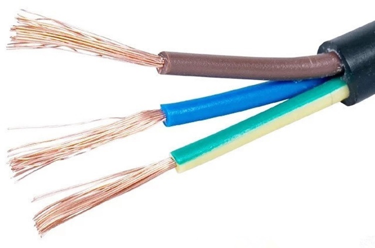
First off, let’s set the general rule we are using copper cables and not something else like CCA speaker wire! These cannot carry the same amount of current and can be dangerous to use (copper speaker wire can be ok).
For Digital LEDs I recommend using the LED Power Usage Sheet combined with the method shown in this livestream!
How important is cable size?
Check out this video (jump links in the description) next to possibly being dangerous (when you don’t use the correct size wires) it can also cause all kinds of problems in your setup from dim, wrong color or flickering LEDs.
Check my video about wire diameter here:
Voltage drop is real!
In this video I show a very clear example of voltage drop on 12v LED strips and how multiple injections help the LEDs run correctly and shine at the brightness they should be, it makes a *BIG* difference! This works the same for analog LED strip or Digital LED strip/string! With digital LEDs it can also cause many more issues then just LEDs that shine less bright!
Designing for worst case scenario
All calculations made are designed for the worst case scenario which is full brightness. Now I realize you won’t be running your LED strips set to full brightness most of the time (or ever really with very high power versions), that’s why you’re using an Analog LED dimmer or Digital LED controller.
Still, I tend to design all my setups in such a way that if I do need full brightness it is at least possible, maybe with a bit of extra voltage drop but that it never turns into a dangerous situation and while also making sure any fault scenarios (short circuit, etc.) are caught and dealt with (fuse for instance) without it turning into a disaster (fire, etc.). Our setups are often left unattended after installing so they need to be able to deal with these kind of situations by themselves too.
For digital LEDs this means I design towards the nominally needed current. You can learn more about how to do that in this article and video here.
For this it’s important to understand the current rating and handling of each individual component (power supply + dimmer/controller + cabling + LED strip/string) can handle the amount of power that CAN be output to them. With those numbers in mind a correct choice can be made when choosing the size fuse, etc.
With that said, please keep reading until you reach the “Are you insane?” section!
How do you size the diameter of the cable you need?
For this I like using a “voltage drop calculator”. Although it won’t tell you what the cable itself is rated for, if you design properly for the current you are expecting to run and then size the fuse accordingly there should always be enough headroom that if a fault condition occurs the fuse pops quicker then that the wire will burn (that’s our goal!).
Quick Glance estimation
Take a look at the following table it will show in a quickly to use overview what size of wire you are looking at for the given amount of current and distance. The table allows for 5% voltage drop over that cable at the given amount of current so that whatever you are powering will get the correct voltage at all times.
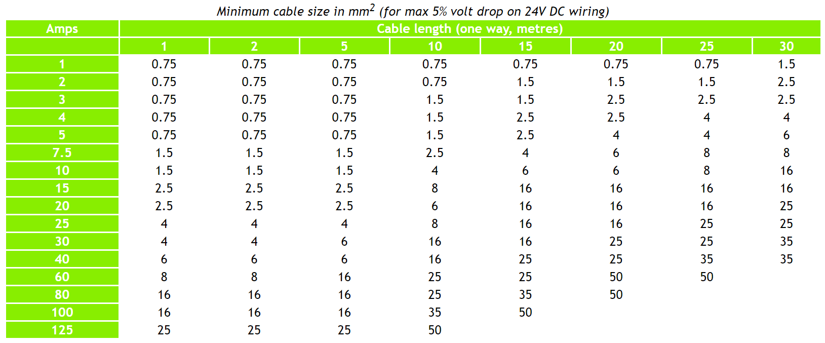
Table borrowed from 24volt.co.uk , want to know in AWG, use this calculator!
Why does Length matter?
The cable diameter is calculated given 2 numbers:
- Amount of current
- Distance
A third one could be amount of voltage drop that is tolerated but in theory any voltage drop is wasted energy, I’ll come back to that in a little bit.
So we all understand that we need to size the cable to the amount of current that we expect, but why does distance matter?
Wire Resistance
The reason voltage drop happens in the first place is because a cable isn’t a 100% perfect conductor of electricity. It has some resistance and this resistance is what causes the voltage drop to happen. Basically any electricity that is run through the cable encounters that resistance and all the “voltage drop” you get as a result is energy converted from electricity into heat!
That is why it’s important to make sure we don’t loose too much energy.
But this also explains why a short cable might be fine for a certain amount of current but a much longer one is not. The resistance accumulates with distance. So every extra bit of cable the electricity needs to travel along generates this resistance and thus more is lost.
Calculating the cable diameter you need
So we know that current (Amps) and length combined can tell us what diameter/size/thickness cable we need. As mentioned above we need 1 more value and that is what we’ll allow to lose as voltage drop. The above table mentions 5% but generally I feel that 10% is ok since we’re calculating for a worst case scenario generally so normal usage will be less current and thus also less voltage drop.
As mentioned before it doesn’t matter if we’re talking about Analog LED strip or Digital LED strip/pixels, power is power and the calculation stays the same. For Digital LED strip and pixels I have a real-world datasheet where you can calculate the amount of power that is expected and there are also rules which make it easier to figure out what you need. I have a dedicated livestream which helps you design your setup for Digital LEDs!
Using the online calculator
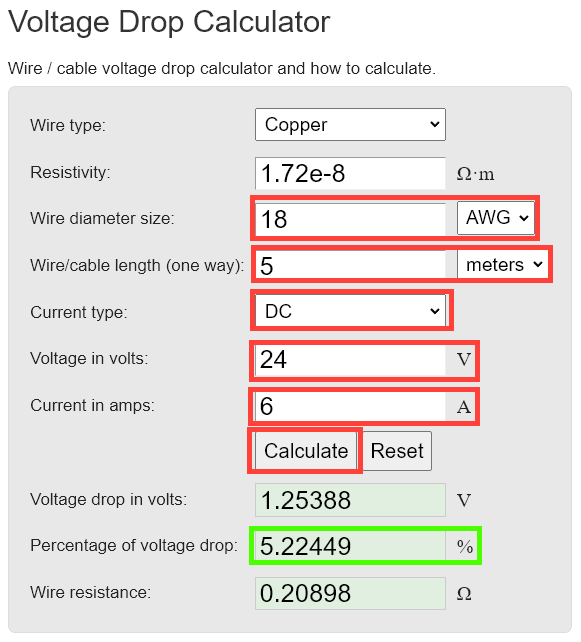
Instead of the above table I like using an online calculator. As mentioned above I find 10% of voltage drop acceptable so let’s do some example calculations!
None of these calculations take power injections into account, in reality you will have to power inject since a single injection is limited to what the strip can take in from a single point!
Analog strip
- 5m/16ft, 12v, Warm White LED strip that uses 14.4w/m from Auxmer
- 5m x 14.4w = 72w total
- 72w / 12v = 6Amps total
- Wires from Analog Dimmer to LED strip are 1m
- 22AWG/0.3mm2 cable is required
- Wires from Analog Dimmer to LED strip are 5m
- 18AWG/0.8mm2 cable is required
- 5m/16ft, 24v, Warm White LED strip that uses 28.8w/m from Auxmer
- 5m x 28.8w = 144w total
- 144w / 24v = 6Amps Total
- Same as above applies!
- The reason is that it’s now 24v and not 12v so we can carry double the amount of energy with the same amount of Amps!
Digital LED strip
- 5m/16ft, 5v, ws2812b from BTF Lighting
- 5m uses max 65w or 13Amps according to the real-world power sheet, we’re going to use the 50% RGB white value which is 32,5w or 6.5Amps
- In reality you can only input 4Amps from an edge connection or 8Amps from a middle connection! These calculations are for cable calculations, not a proper LED setup!
- Wires from Digital LED controller to strip are 1m
- 20AWG/0.5mm2
- Wires from Digital LED controller to strip are 3m
- 16AWG/1.3mm2
- Wires from Digital LED controller to strip are 5m
- 14AWG/2.0mm2
- Wires from Digital LED controller to strip are 10m
- 11AWG/4.1mm2
- 5m uses max 65w or 13Amps according to the real-world power sheet, we’re going to use the 50% RGB white value which is 32,5w or 6.5Amps
- 5m/16ft, 12v, ws2815 from BTF lighting
- 5m uses max 50w or 4,166Amps according to the real-world power sheet, we can’t use the 50% RGB white rule for this because of the unique properties of ws2815!
- In reality you can only input 4Amps from an edge connection or 8Amps from a middle connection! These calculations are for cable calculations, not a proper LED setup!
- Wires from Digital LED controller to strip are 1m
- 22AWG/0.3mm2
- Wires from Digital LED controller to strip are 3m
- 20AWG/0.5mm2
- Wires from Digital LED controller to strip are 5m
- 18AWG/0.8mm2
- Wires from Digital LED controller to strip are 10m
- 17AWG/4.1mm2
- 5m uses max 50w or 4,166Amps according to the real-world power sheet, we can’t use the 50% RGB white rule for this because of the unique properties of ws2815!
Big difference in size needed?
Why is there such a big difference in the wire size needed between the 2 digital LED examples while the 5v even uses less watts but requires thicker cable? The reason for this is because of the voltage. If we have the rule that we can only lose max 10% of voltage over the cable this means 0.5v for a 5v setup but 1.2v for a 12v setup! Combined with the watts being about the same but the amount of Amps being considerable less it means you can use much thinner cables for the ws2815 setup!
But all LED strip comes with really thin cables?!
According to the above calculations you need some decent diameter cables to connect you LED strips to your boards! Most LED strips come with some short leads which have a fraction of the thickness, so how do the above calculations make sense?
As mentioned above, cable diameter scales directly with distance. For a 10cm lead you aren’t going to need 10AWG/2.5mm2 wire. Something like 22AWG/0.3mm2 (or even less) will work just fine.
This means that if you need to step-down in wire diameter to for instance connect it to a terminal or solder it to a strip as long as you keep that part short it’s no problem and it won’t affect the voltage drop over the whole cable in a meaningful way. I have also tested and you don’t need to replace the leads that generally come with LED strip since they are so short, the voltage drop on an LED strip will cause an effect where it can only take in so much current from a single spot and after that you need injection wires to a spot further along the LED strip to get more power into it.
Personally I like using 18AWG/0.8mm2 wire a lot! This is about the thickest/highest diameter size wire you can comfortably solder to your LED strips and it allows for a good amount of current and you don’t have to worry about relatively short distance up to 1m/3ft to 2m/6ft even if it’s for 5v strip!
If you are still looking for cable after reading this and then calculating the cable you need, see the Tools and Equipment page I have listed several different types there which can be used for power or signal wires (signal wires can be a lot thinner!).
Additional information
Sometimes there are special where cases you need to take into account when calculating wire thickness.
Fuses
Use fuses! There is no way around it, we’re dealing with a lot of energy on some of these cables. And while we calculate that during normal operation they carry the amount of current we need in a fault condition (short circuit, etc.) this can suddenly double, triple or even more. If the cable isn’t rated for this (it generally isn’t) it can melt and start a fire! To prevent this we add a fuse inline which is rated slightly above the expected current. If suddenly a lot more current is drawn the line is disconnected by the fuse popping and the situation is safe again.
Please also see this dedicated article about fuses (mainly oriented towards Analog LED strip, all my digital controllers have fusing capabilities built-in!).
Power injections or “double feeding” a LED strip
(Mainly applies to Analog LED strip!)
If you are, for instance, single feeding a 100w LED strip which runs at 24v and needs 5 meters of cable this requires 4,16A of power and thus a wire thickness of 0.75mm2 to transfer it over those 5 meters. If you however double feed the cable (from both ends) the requirement per cable is only ~2A so thinner cables can be used!
*Power distribution is never 100% equal and it’s good practice making sure both ends can handle the full load, maybe use 2/3rd of the thickness instead of half for instance
Analog RGB(W)
When using RGB(W) strip you have 4 negative wires but only a single positive wire. To be able to handle the same amount of current all the negative wires can handle, the positive wire should in theory be 4 times thicker than the negative wires. In reality that would make for a very thick (and thus expensive) cable so generally twice the size cable is recommended. If each LED strip color can handle say 1Amps using 24v, make sure the positive + cable can handle at least 2Amps but preferably more.
Alternate wiring ways
For instance in this QuinLED-Quad article I have diagrams of how it can be hooked up optimally. There are however different ways that sometimes surface on the internet, I mostly don’t recommend these but they are:
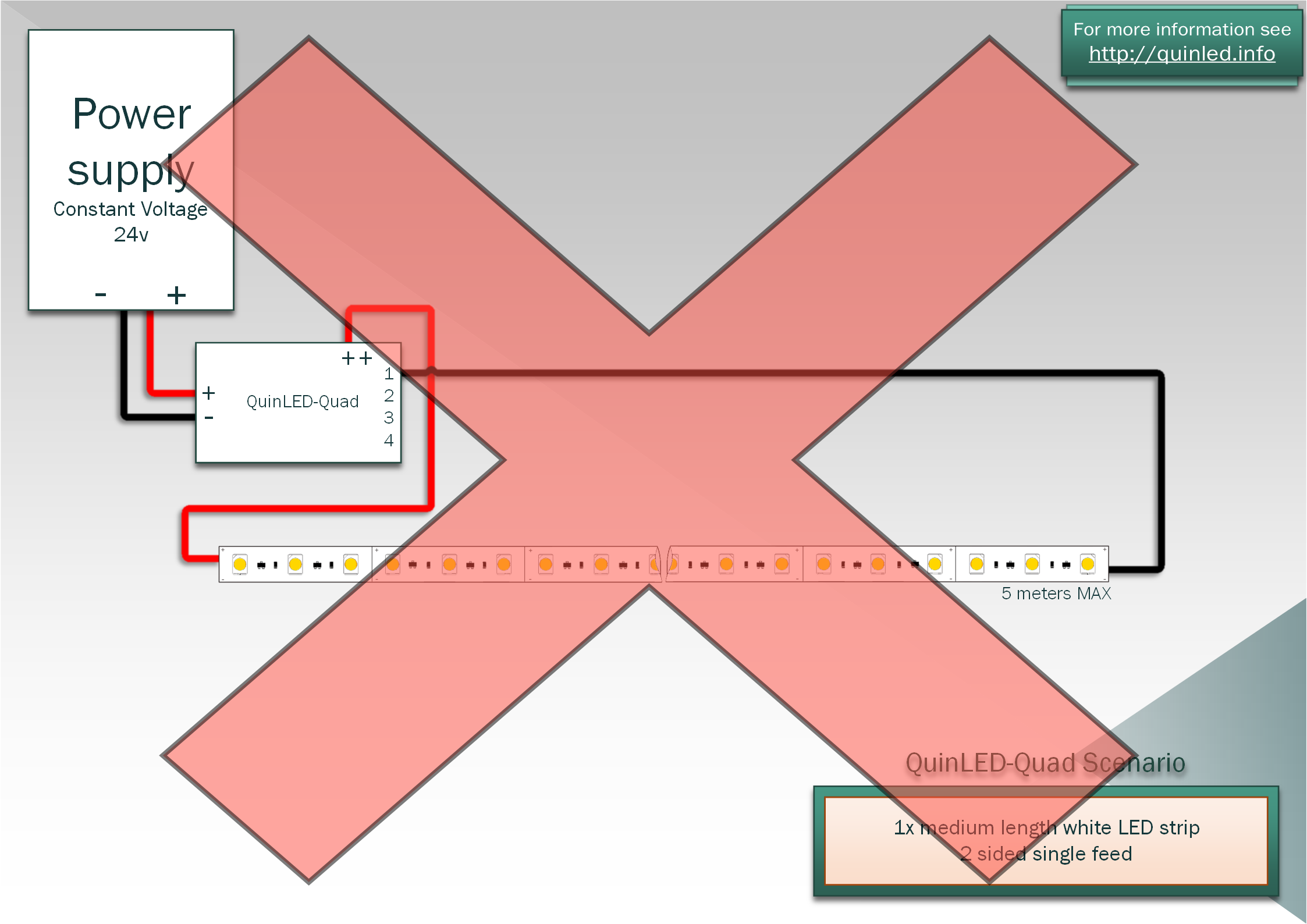
2 sided single feed
If you want to make sure all LEDs within a strip are evenly lit you can connect positive on one end and the negative current on the other side of the LED strip. This way power always needs to travel the same amount of distance through the strip and in theory voltage drop will thus also always be the same for each LED. Although this is a viable way of doing it, especially in larger LED installations this can be confusing to hook up. This also doesn’t solve the problem of voltage drop within the LED strip but basically works around it by using the effect instead of solving it. The result, although evenly lit will still result in dimmer LEDs and also still cause a lot of extra heat because of all the current (or rather voltage dropping and thus turning into heat) traveling through the LED strip.
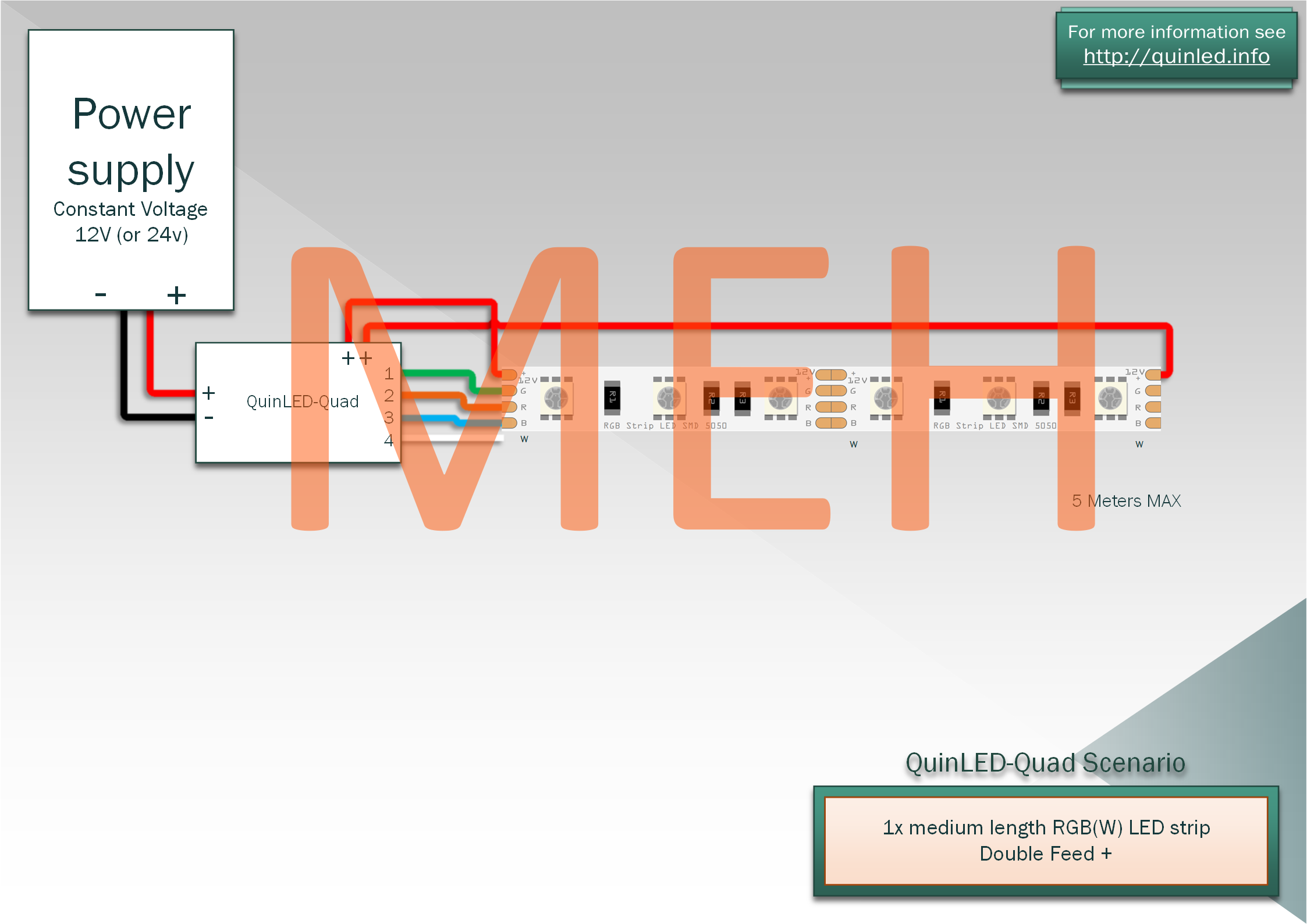
Only double feeding positive +
When using RGBW strip, each color (Red, Green, Blue and White) have their own negative line going to the strip. The positive line/rail is shared among them. In my opinion you need to make sure that the positive rail is thicker and uses thicker cables so to be able to match the 4 negative rails on full brightness (RGB displaying white + white). In reality the cables connected to the LED strips are all the same thickness so the positive cable needs to conduct a lot more current then the other cables. A way to fix this is to only run a positive cable to the other side of the strip and only double feed the positive rail. Since the current running through the negative wires is a lot less, it’s voltage should drop off less and sometimes you can get away with only double feeding the positive rails that way.
Personally I’d advise, if you are planning this, to plan for double feeding all the rails (positive and negative) or to middle feed to prevent an imbalance in the strip. This will also make sure you get the actual intended maximum brightness out of the strip and don’t cause a very high heat build-up at the side where all the negative wires are connected. With that said, for some projects only double feeding the positive current might be enough and workable.
Here is an example how to hook this up using the QuinLED-Quad: