
What does a fuse do and why would you want to use them?
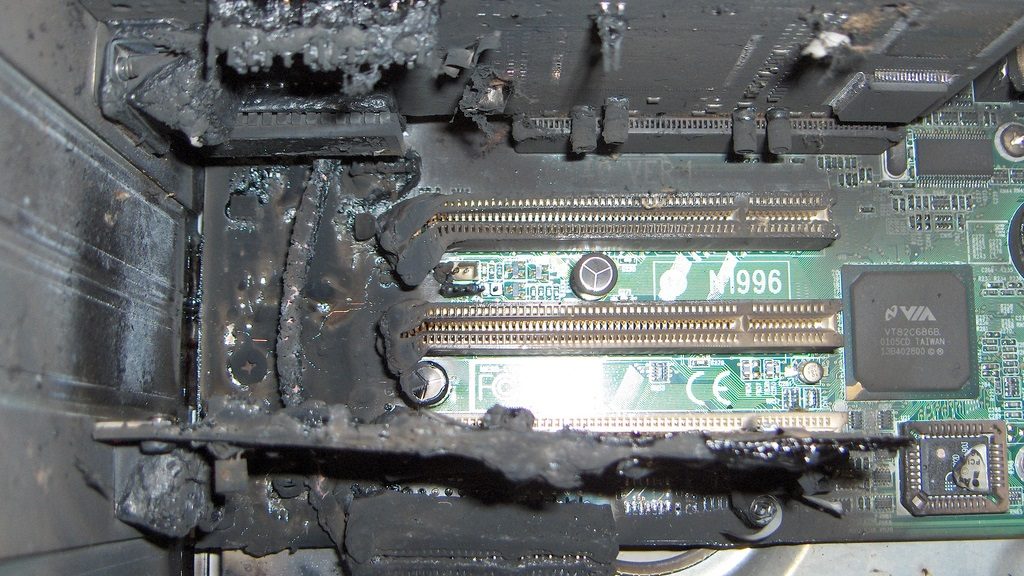
Fuses serve the purpose of little protection devices that will limit current (cut off) when something goes wrong. In a very basic form, if your device should only draw a maximum of 2A and it suddenly tries to draw 10A, something is very wrong and if it’s correctly fused, the fuse will break and somewhat protect the device but more importantly, prevent a potential fire. You can then correct the problem and easily replace the cheap fuse and be up and running again!
My current boards do not have any fuses on them, fuses are not necessary in every project and I expect people that need a fuse to do so externally in their projects. That doesn’t rule out making boards that has on it in the future though, but right now I advise you to do so externally if desired/needed.
Do you need a fuse in your project?
If you need an additional fuse or not depends on your project and the power supply you are using. In theory all power supplies already have a fuse so if anything goes wrong it should cut out using “Over Current Protection” or when that doesn’t work, by blowing its internal fuse. But there are cases where this isn’t going to work or rather, can still result in a dangerous situation.
On large installs that use many Amps you often use a single high Amperage power supply, for instance for 5v or 12v people sometimes use PC power supplies. These come in high wattages so something like 60ow is available for under a 100$ and can still be pretty quiet even with having a fan inside of it. But that means that if we’re talking 12v this power supply will have a fuse that’s rated higher than 50 Amps. That also means that if something goes wrong, the current would need to go above 50A for the fuse in the power supply to blow. Higher end power supplies also have something called “Over Current Protection” but since it’s rated for a PC it probably won’t kick in either. So if a short occurs in your strip or wiring it could be pulling 25A of current without the power supply cutting out and thus likely causing a fire because it keeps providing energy and thus probably generating (a lot of) heat as a result of a short in the wiring or strip.
So in that scenario I would very much recommend using seperate fuses for all LED lights/channels connected! This isn’t limited to PC power supplies but it’s an easy example, anything that can deliver over 150w to 200w falls in that category.
If you want to learn a bit more about why this is and some tests, check out this article.
Extra fuses not always required though
But there is also the flip side of the above scenario and that is when your power supply isn’t rated in the hundreds of watts. For instance if you are running a 40w LED light strip and have a 50w power supply connected which has a fuse inside of it, you are going to be fine. If anything goes wrong the power supply should protect you and adding an extra fuse probably won’t add too much in that scenario.
TL;DR when to use a fuse
If you are using a power supply that can deliver more than 150/200w continuously you should consider adding fuses behind it to make sure that when some wires cross or a part malfunctions it can’t create a fire.

How to calculate LED light fuses
So first off, fuses are only put on the positive lines when talking DC. That is actually convenient because Analog LED dimming with PWM is done using the negative lines!
So if you are using a very high wattage power supply to run multiple dimmers and/or LED channels, I advise to put up a fuse per LED channel you are running. Often in a house install each of these lines will draw a different wattage and thus amperage and you need to fuse each of those channels/lines accordingly with the correct amperage. So let’s say you are running the following:
I’m going to assume you are running 24v LED strip:
- 100w max with 24v = 4,2A load
- 50w max with 24v = 2,1A load
- 180w max with 24v = 7,5A load
With those values in mind we don’t want to use a fuse that’s exactly rated for the current we are going to be running through it so you need to calculate in some headroom. So for the 4,2A channel I would probably use a 5A fuse, for the 2,1A channel I would use a 3A fuse and for the 7,5A I would use a 10A fuse. These values are pure guesswork but in the end you want a value that isn’t too high because it gives less protection but too low values might pop the fuse while nothing is wrong.
What type of fuse to use
Any type of fuse that’s suited for 12v/24v is suitable to be used, it’s up to you what form factor you find easiest to use in your project. Personally I like using car fuses because those have the correct voltage rating and because they are a mass produced product they are very cheap! They also come in lots of different ratings from 1A up to 40A and everything in between, making it very easy to correctly fuse all your channels.
Higher voltage?
If you want to use fuses with your COB LEDs for instance take a good look at the voltage. These ATO style car fuses are most often rated up to 32v. You can get them in a higher voltage rating but you will need to search around for them a bit. The reason the voltage is important is because the higher the voltage gets the bigger the gap a current can traverse. When the fuse breaks because of a too high Amperage the fuse manufacturer can only guarantee the now broken fuse to hold up against a certain voltage. If you exceed that rating current may jump the gap and still create a short or a problem!

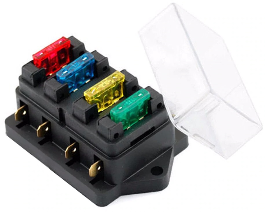
Picture from www.autofix.com.au
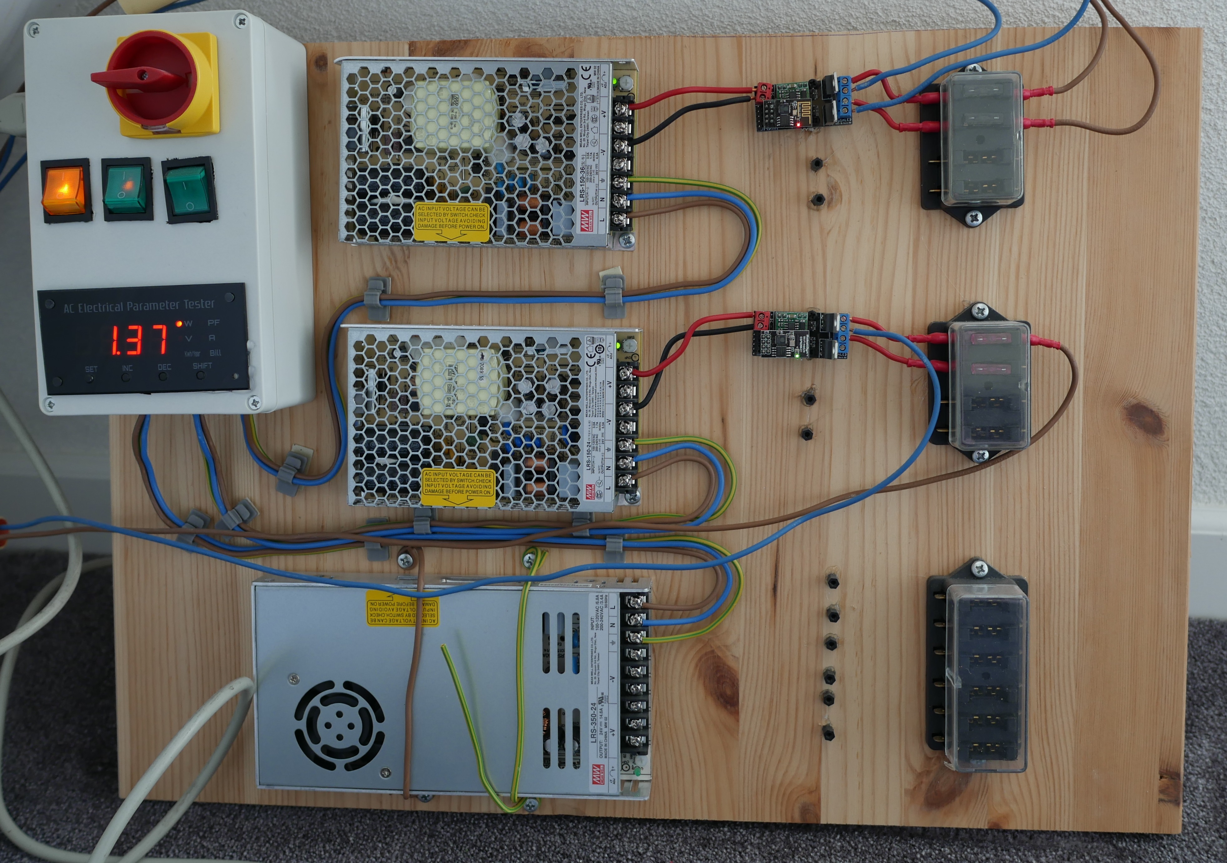
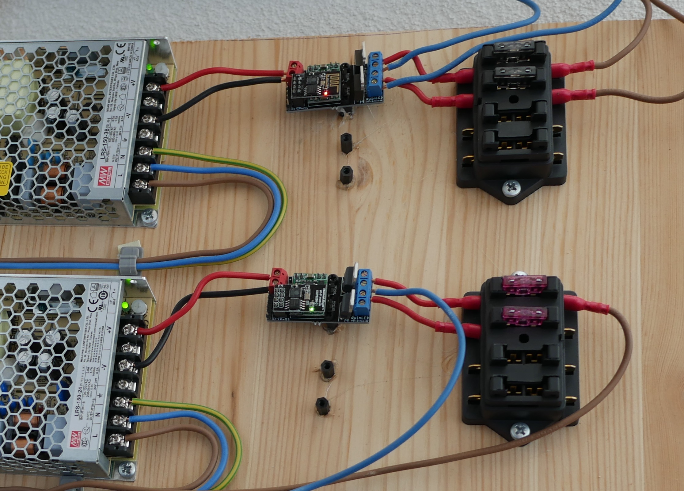
These car fuses (The yellow one in the picture above) can be used in cheap holders that can hold 4, 6 or even 12 fuses at the same time making wiring easier! A while back I built a few of these boards and I use these in my home. This board has a shuco input plug (which has its own fuse) and the runs into a project box where I have a switch for each power supply and a wattage meter built-in. From there I run seperate cables to each of the power supplies and connected to those are QuinLED-OG models of which the positive lines run through a case fuse holder in which I have the fuses for that particular LED strip or downlights.
Wiring Diagram
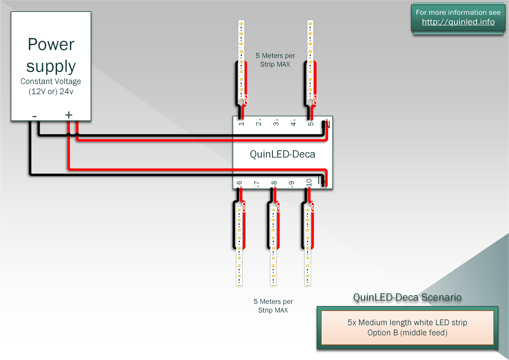
As mentioned above while wiring you only need to worry about the positive voltage lines. Below is an example diagram of how you can add fuses to your setup, they are different from Analog LEDs and Digital LED strips. For analog LED strips the negative line needs to go through the dimmer to use PWM dimming, the positive however does not. For Digital LEDs neither line needs to go through the dimmer but we still only fuse the positive line.
Analog LED dimmers
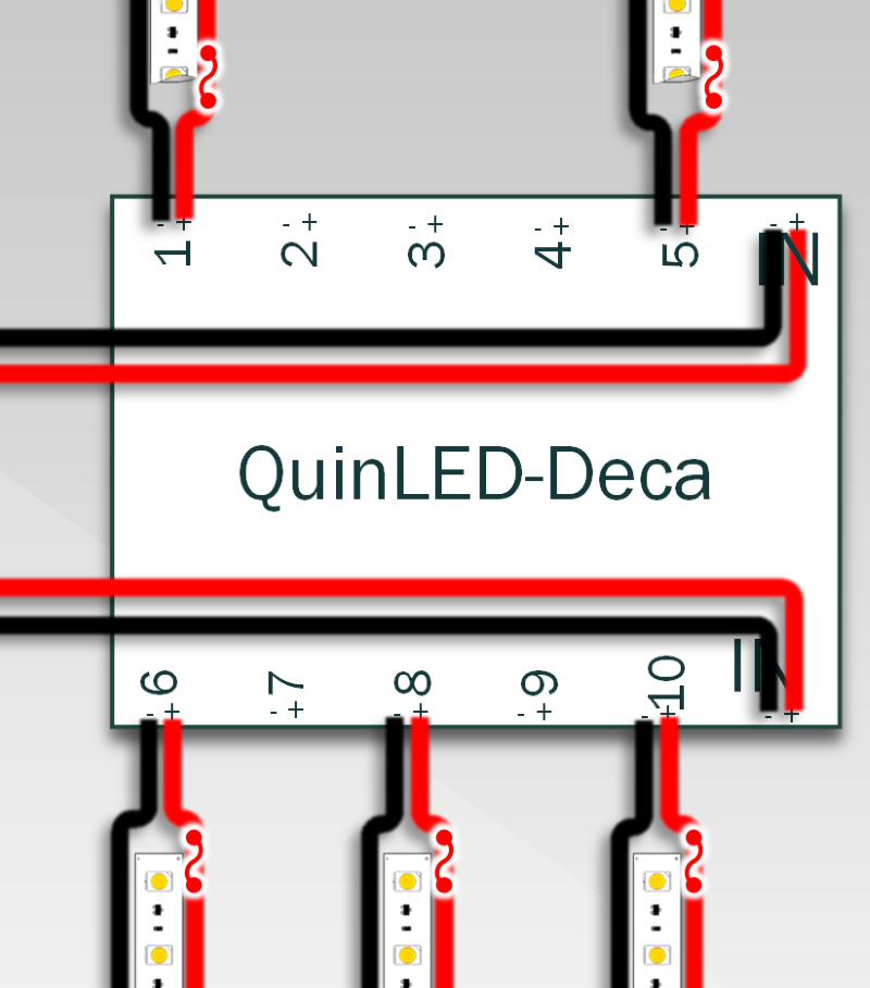
This is an example of a few LED strips connected to the QuinLED-Deca using a wiring diagram where all the strips are being middle fed. The placement of the fuse inside of the positive cable doesn’t really matter (it will work anywhere) although it’s often best and most convenient to place it closest to the controller like I did in the above example.
Digital Controllers
For digital controllers the placement is basically the same. Once all information about the digital controllers is up I will update this article with some extra diagrams.
Shopping links
Here are some of the components and parts I like using when adding fuses to my install. For all of them using crimped on connectors is the easiest way to use them, check out my additional tools and equipment page for those. On the cheaper block you can use the female blade connectors to slide on the male blades and on the more expensive version you can use ring terminals you can then screw down to make them 100% secure!
Cheap Car Fuse Holders
Deluxe Car Fuse Holders and distribution panel!
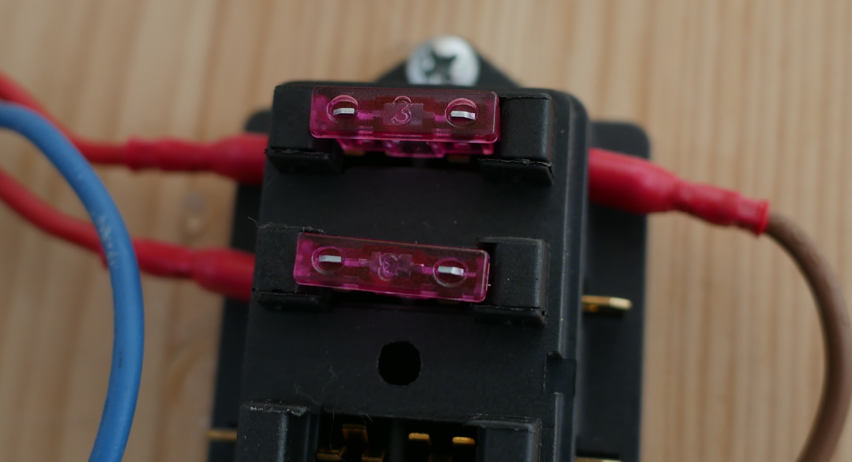
If you want to make it really robust and well let’s be honest, cool looking, these Deluxe Car fuse holders are for you! They are very robust and even provide a little light so you can quickly see if a fuse is blown or not. It allows you to connect a very beefy cable (or multiple cables from multiple terminals) from your power supply on both the negative and positive side. As mentioned before we are only going to fuse the Positive side but you need to connect a little line to the negative side so that the onboard lights will work. No current is going to be drawn through that though because out negative lines are bypassing this fuse holder because each channel will have it’s own dimmed PWM value.
This fuse holder also serves as a distribution panel which makes it very convenient to use when you are running a lot of high power LED channels! But depending on what kind of LEDs you are using you can run either Positive and Negative through the block (in case of digital LEDs using a QuinLED-Dig-Uno) or only run positive through the block (in the case of Analog LEDs using a QuinLED-Quad or QuinLED-Deca) and all negative channels should run through the (QuinLED) dimmer and then directly to the LED lights since that’s where the analog PWM dimming takes place.

Some ATO sized Fuses
Although these these fuse holders can take the mini low-profile, mini and normal size fuses, for the fuse holders above I recommend getting the full size “ATO” fuses.
![]() ATO (Full) Size fuse assortment box (140 Pcs or more)
ATO (Full) Size fuse assortment box (140 Pcs or more)
End Remarks
This is the most convenient way I’ve been able to think of to an extra fuse your LED projects where needed. I’ve been using this way in my setup for the past few years and this has worked well for me. It’s a bit of extra work but if you are running these lights 24Hrs a day in your house as your main lighting system you want to protect your boards and well, your house. If even only one of these fuses can prevent a fire it was all worth it.