QuinLED Diff-Adv Receiver-Midpoint Switches guide
Back to QuinLED Diff-Adv main page
The QuinLED Diff-Adv system is designed around sender and receiver boards. Instead of making the receiver boards endpoints, so where the cable with the (up to) 4 LED channels on it ends and thus basically you have to have 4 LED channels broken out at that location, the system is designed around having midpoint receiver boards. With these you can have a single chain of UTP cables that has 4 separate LED data channels on there but by using Receiver-Midpoint-1 or Receiver-Midpoint-2 boards you can determine where you want these channels to be broken out. You can even choose to have the same channel broken out at multiple locations having them behave exactly the same!
To be able to select what channel you want to output at which location there are 4 switches per Receiver-Midpoint board. For Receiver-Midpoint-1 allows you to extract 1 channel and the Receiver-Midpoint-2 allows you to extract up to 2 channels (but it can also be used to extract 1 LED data channel for a location where you need power distribution and fusing!).
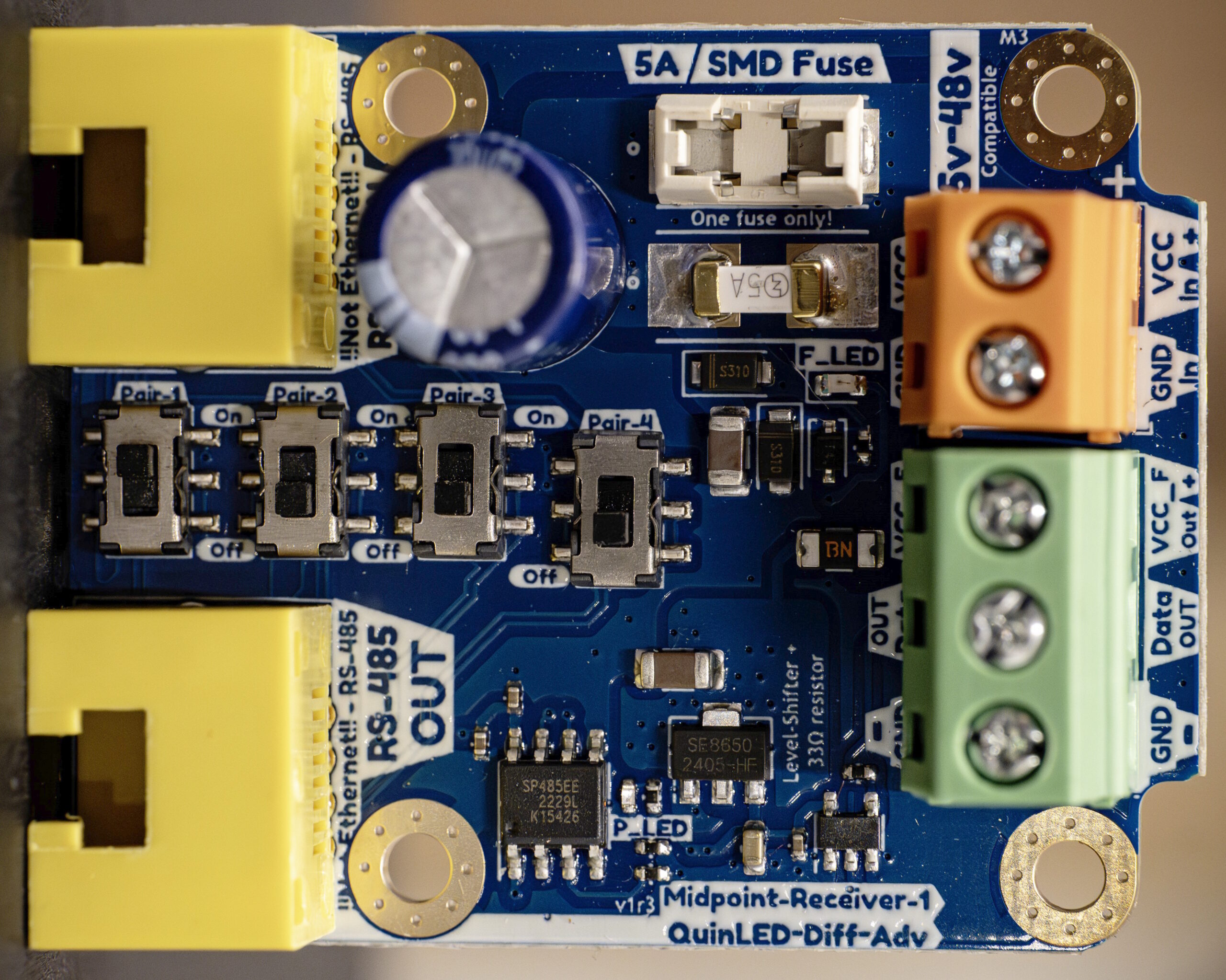
Switches on the Receiver-Midpoint-1
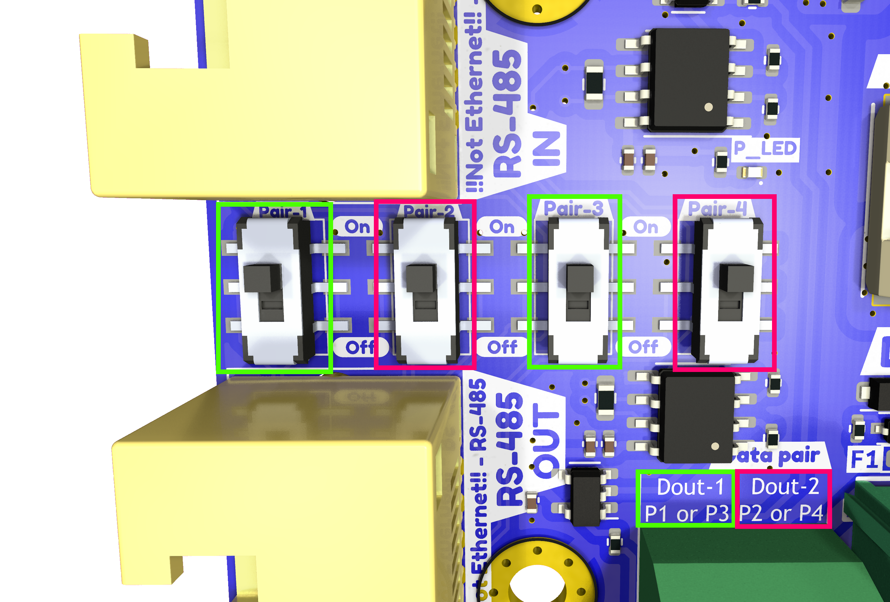
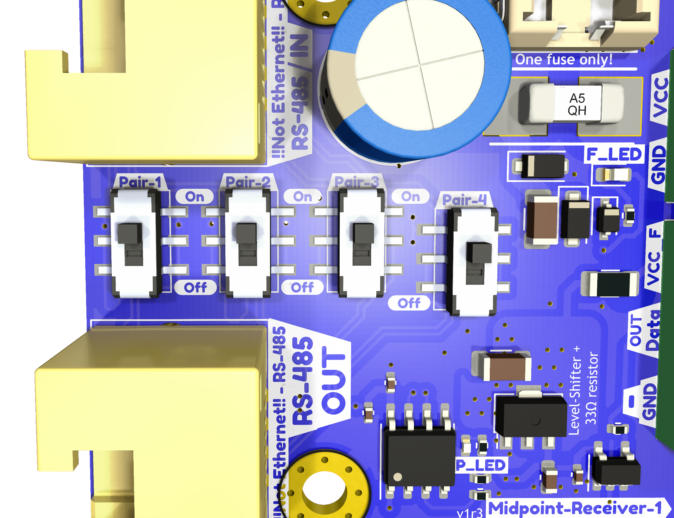
On the Receiver-Midpoint-1 you will find 4 switches. One switch can be active at the same time, turning multiple switches on will make the LED data output come out corrupted.
Other then that on the Receiver-Midpoint-1 it’s quite simple, select the channel you wish (corresponds to the input channels on the Sender-4 board) and that will come out of the LED data output!
Switches on the Receiver-Midpoint-2
On the Receiver-Midpoint-2 the switches are slightly more complicated because the board has 2 LED data outputs. Because of this the switches are grouped in 2 banks.
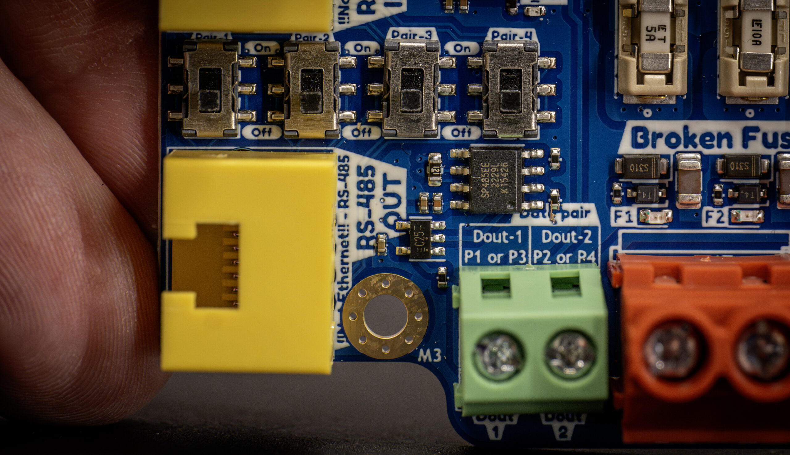
- LED output 1 can be switched to
- Pair1
- Pair3
- LED output 2 can be switched to
- Pair2
- Pair4
This means you can have 2 outputs active at the same time as long as they are not in the same group!