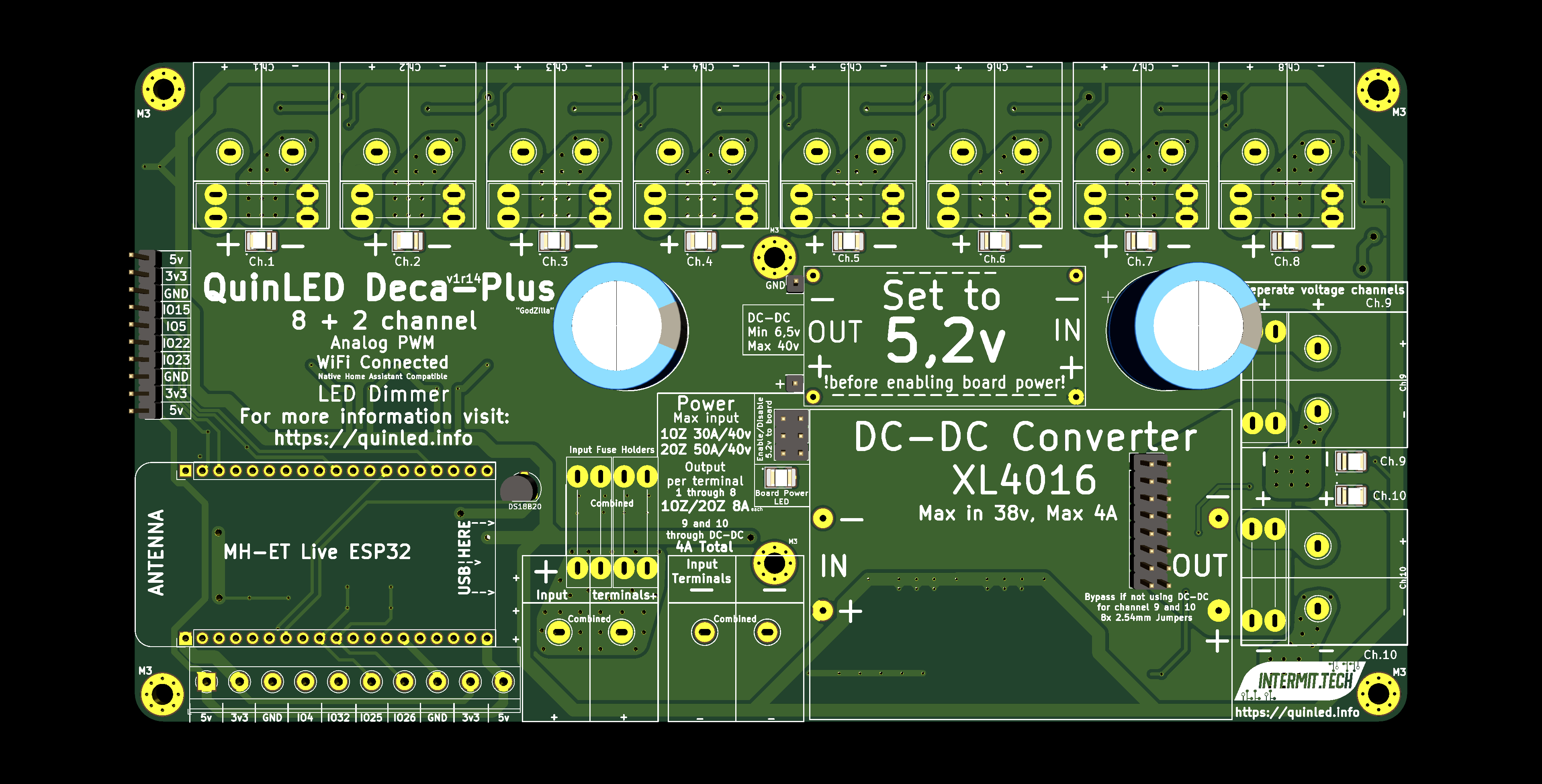
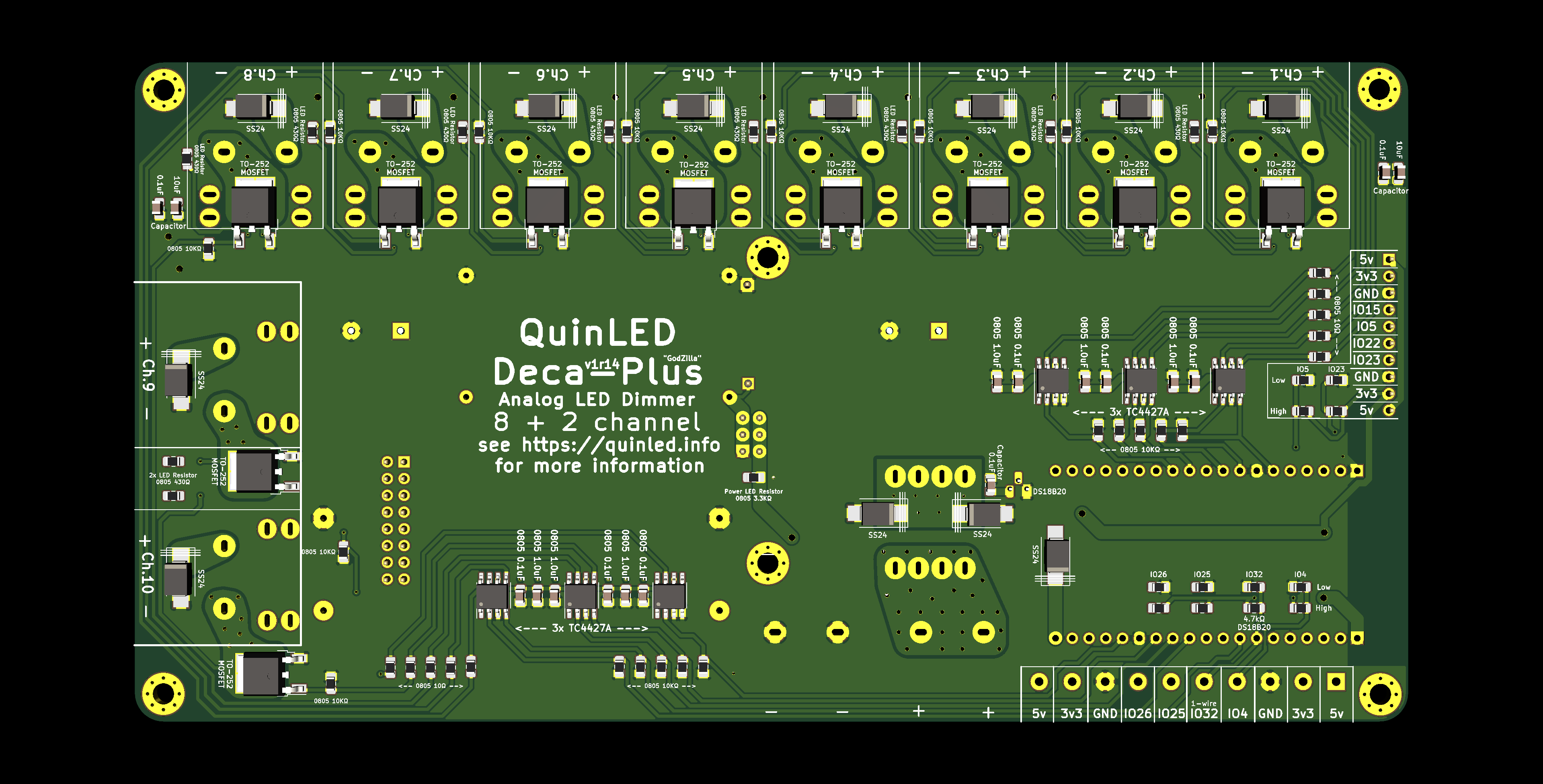
QuinLED-Deca-Plus
2021 update – This project has currently been cancelled and is being re-envisioned in a different form!
QuinLED-Deca-Plus is a bigger brother to the normal QuinLED-Deca, it’s still a 10 Channel WiFi connected PWM LED dimmer but it has some more features making it more suited for “whole home lighting” then running a few RGB strips. The main design goal for this board board was being able to run several high powered white LED strips or other lights with very high power handling per channel + including some additional safety features when dealing with that amount of power.
This board accepts up to 40v input and output voltage making it suitable for a wide range of LED lights (from strips to COB modules). A unique feature is that you can split off two of the onboard channels through a beefy “onboard” voltage converter and set those channels to use a different voltage then the other 8. That way you can for instance run 24V LED strips combined with 2 channels 12v LED strips, or run the main channels at 36v from a 36v power supply for COB downlights, but still run a 24v or 12v LED strips from the 2 separate channels, all without the need of an extra power supply! It also has a bypass if you don’t want to use this feature to use those 2 channels with the same voltage as the other 8. The board also features extra large screw terminals making installation and wiring with thicker wires easier.
More Advanced DIY
The design of this board but specifically the build skills and equipment required for this board are a bit more advanced then my other boards (QuinLED-Quad, QuinLED-Deca, QuinLED-Dig-Uno). I would highly recommend a hot air station/Oven and solder paste since there are a lot of SMD components involved.
The build time required is also a lot more per board, prepare to spend 4 to 8 hours per board!
Pre-Built?
If people who can’t solder this board themselves (or don’t have the equipment/time) still want it, drop me a line using the contact form, on YouTube or through Discord. If I receive enough response I’ll invest time in making several versions available next to the full DIY one. DIY will always remain the cheapest way to do it but for this board I can imagine the following other options which would still make it feasible to run this board if they want to:
- Pre-Assembled: SMD Components only
- This way you will receive most (if not all) SMD components on the board already and you only need to finish it with (large) through-hole components
- Pre-Assembled: Fully built
- This board will be ready to go (flash) when you receive it, all components are soldered onto the board
Again, let me know through either the contact form or on Discord if you’d be interested in this and I’ll make it happen! 😀
Features
- MH-ET-Live ESP32 development board
- Dual-Core CPU with plenty of memory and hardware timers for PWM generation
- WiFi 2.4Ghz 802.11 N connectivity
- Wide software compatibility through Arduino IDE, Micropython or other distributions
- Excellent and easy ESPhome firmware to use with Home Assistant (with configuration examples)
- Onboard Micro-USB port and Reboot/EN switches
- 10 channels with TO-252 SMD MOSFETs extra high power handling and PWM dimming
- Tested 1.2KHz PWM dimming frequency on all channels (recommended 40kHz or 120kHz)
- Onboard MOSFET gate drivers to raise the GPIOs 3.3v to 5.2v to drive MOSFETs for high amperage loads and granular PWM control
- 10 independent dimming channels each having their own beefy +/- terminal pair on the board
- 2 channels can use the same voltage or use an optional onboard voltage converter to buck down convert them to a different voltage
- Up to 8A per channel output!
- Runs full 24v 5 meter 28.8w/m White LED strip without issues!
- Fuses everywhere
- Board power input fuses
- Per channel output fuse
- Flyback “Reverse polarity” protection Diodes per channel and main input
- Also enables you to PWM fans, pumps, etc.
- 2x Dual input terminal for maximum power input (easily converted to barrel plugs if desired)
- Allows for multiple connections from the same power supply
- Voltage input and output between ~6.5v to 40v!
- Onboard DS18B20 temperature sensor
- 2 Onboard large filtering caps to minimize power supply switching noise
- 4x GPIO in/outputs available through screw terminals (One is shared with One-Wire bus of DS18B20 Temperature sensor)
- Together with 2x 5v + 2x 3.3v + 2x GND screw terminals
- 4x GPIO in/outputs available through pin header (for dupont cables)
- Together with 2x 5v + 2x 3.3v + 2x GND pin headers
- 6x Mounting holes
- 6x M3
- Non-Grounded
- 6x M3
- Large size
- Fully assembled the size is about 20cm wide by 10cm length with a height of 5cm
p.s. At one point an Ethernet port was part of this board but this feature has been scrapped because of technical difficulties getting it to work reliably!
[Finished board image here]
Power handling
The layout, component choice and copper layers on the board have been heavily optimized for maximum power handling. However total power handling of the board does still depend on the amount of copper that is applied to the PCB. Generally these values are 1OZ by default or 2OZ if you pay extra. Depending on your needs you need to select the right amount of copper you need in your boards, please see the below table to calculate your situation.
To make multiple connections from a single high amperage power supply easier (Most power supplies have multiple positive and negative terminals!), the board has 2x + and 2x – input terminals. Both are connected together and each will power all of the outputs independently or together, the same goes for the two fuses. For high power applications it’s very much recommended to hook up both power input ports to your power supply to share the load over multiple output (of power supply), wires, fuses and input terminals!
*One board only needs a single power connection, for higher loads use both power connectors to the same power supply!
*Hooking up multiple power supplies is possible, but not recommended! Research before doing so!
Maximum input/output voltage
The QuinLED-Deca-Plus uses an auto-scaling (Once set) DC-DC converter for it’s onboard electronics. It and the MOSFETs can accept a maximum of 40v, it requires a minimum of 6.5v to operate correctly.
*When using onboard DC-DC converter for 2 separate channels it is recommended to not feed it above 38v
Maximum total power input
[Use 2 power connectors and fuses for over 15A]
| 1 OZ copper | 2 OZ copper | |
| ~30 Amps | ~50 Amps | |
| 12v | 360w | 600w |
| 24v | 720w | 1200w |
| 36v | 1080w | 1800w |
| 48v | 1440w | 2400w |
Max per port output
| 1 OZ copper | 2 OZ copper | |
| 8 Amps | 8 Amps | |
| 12v | 96w | 96w |
| 24v | 192w | 192w |
| 36v | 288w | 288w |
| 48v | 384w | 384w |


