QuinLED-Dig-Quad Wiring Guide
Wiring the QuinLED-Dig-Quad can be a bit more complex then the QuinLED-Dig-Uno because there are lots more ports and options available. This page will take you through what most of the ports on the board do and then later shows you some example configurations and the wiring for it.
If you have questions about the wiring or a custom scenario, Discord is the best place to ask for advice!
QuinLED-Dig-Quad Ports
Input terminals
(Normal configuration)
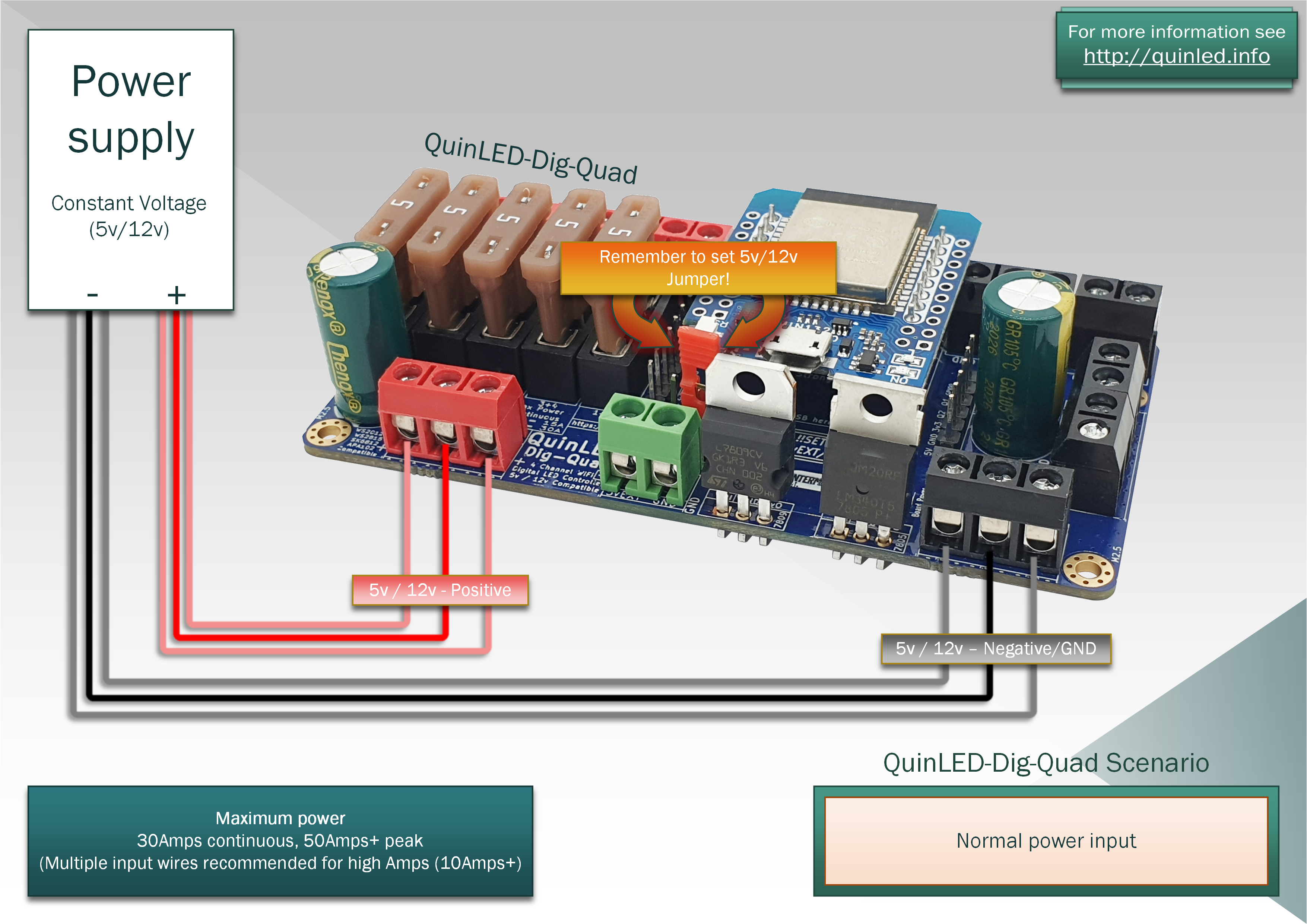 For a normal situation you connect 1 or more positive and negative wires to the input terminals (3 in a row). Everything works with a single cable in each but once you start using more power and if your power supply has multiple terminals available, it’s advised to add parallel wires from the same power supply to the QuinLED-Dig-Quad board.
*Please set the Jumper to 5v or 12v before powering on the board!
*Do not connect wires from multiple power supplies to a single QuinLED-Dig-Quad!
Input terminals (5vEXT)
Setup with a big LED power supply and small 5v phone charger board power supply
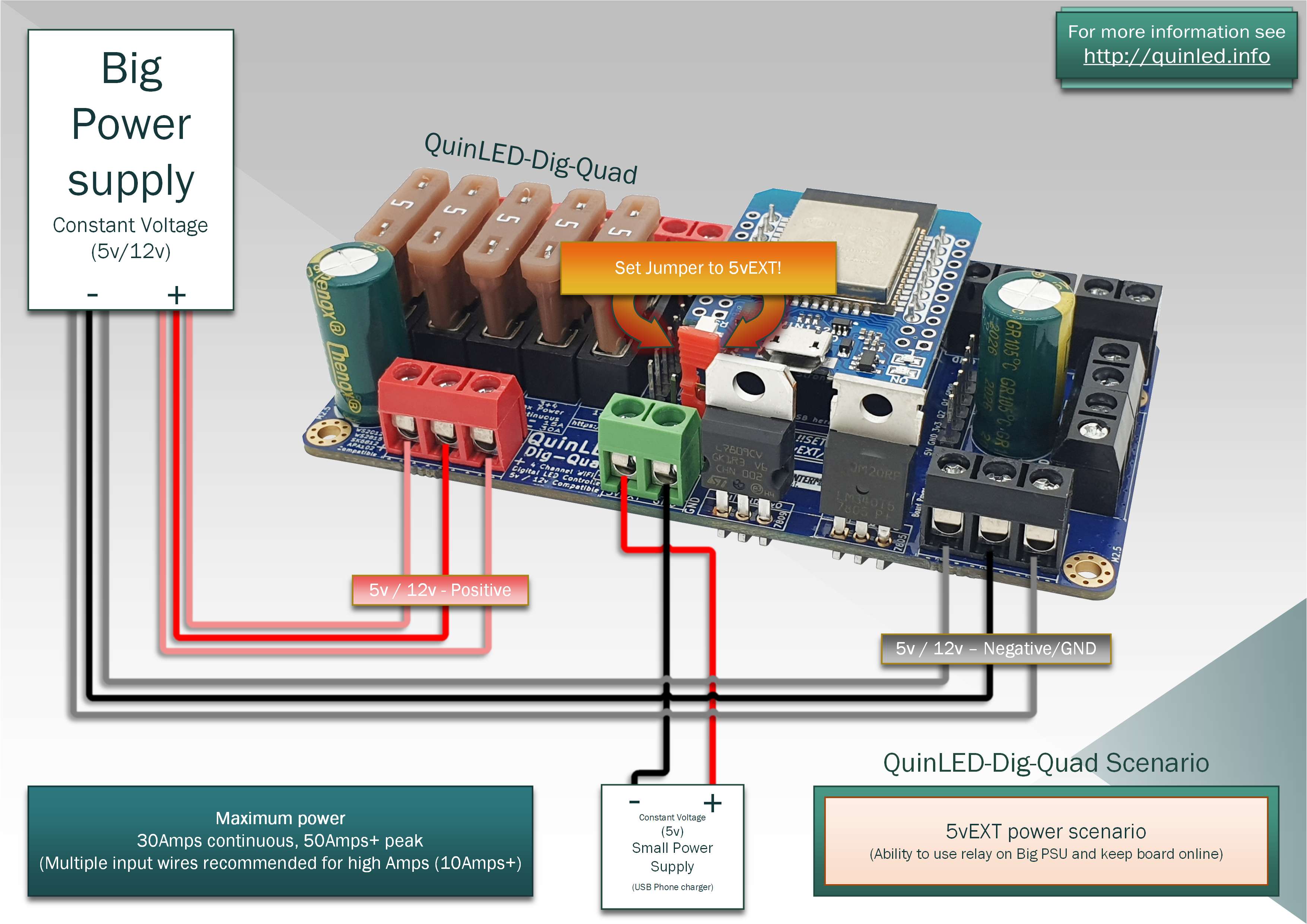 In this scenario we use 2 power supplies (I know I just said not to do that!). But it’s a special scenario where you set the jumper to the 5vEXT position. This allows you to connect a big 5v/12v power supply for the LEDs and a separate small 5v power supply (like an old phone charger) to power the onboard electronics on the board only. This configuration especially makes sense after you connect an AC relay before the big LED power supply so that the board only sips power with the LEDs turned off but does stay online! Please check out the following article for the QuinLED-Dig-Uno how to hook that up in regards to the relay.
Jumper positions
Please note:
Pre-Assembled version no longer has any jumpers it has auto voltage selection (5v-24v)!
DIY version has changed jumper layout, please see here
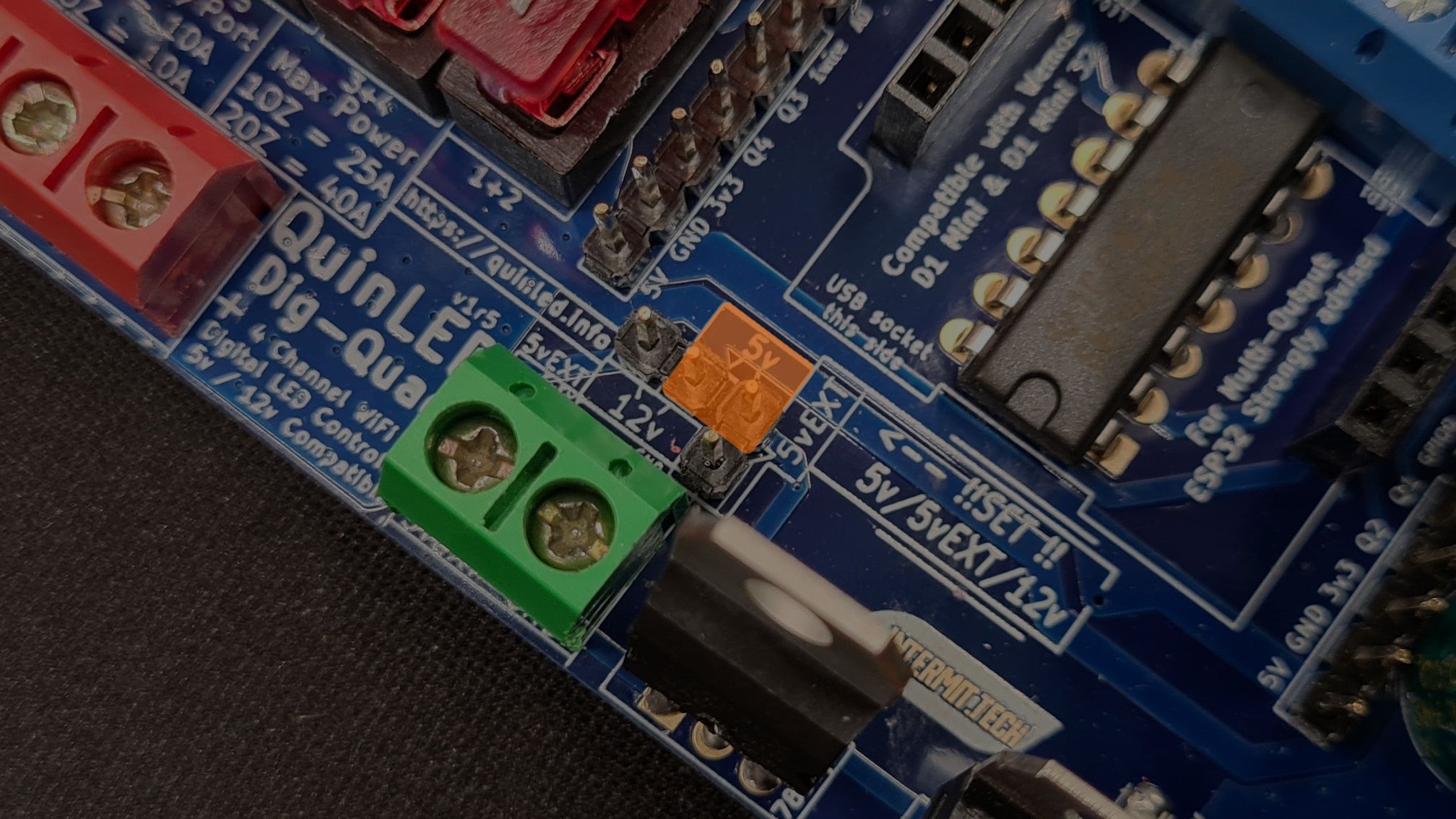 5v in
5v in
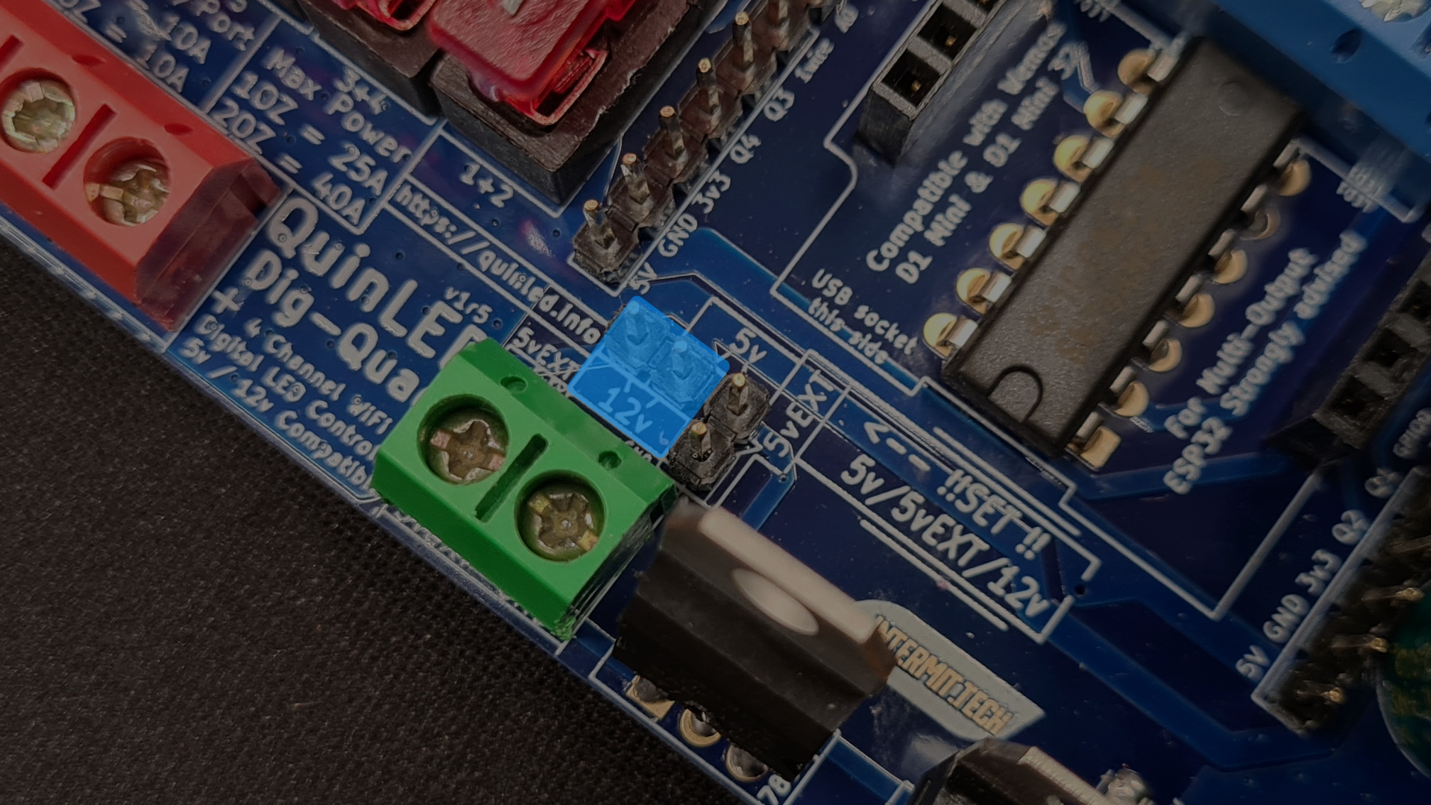 12v in
 5vEXT configuration
Output terminals
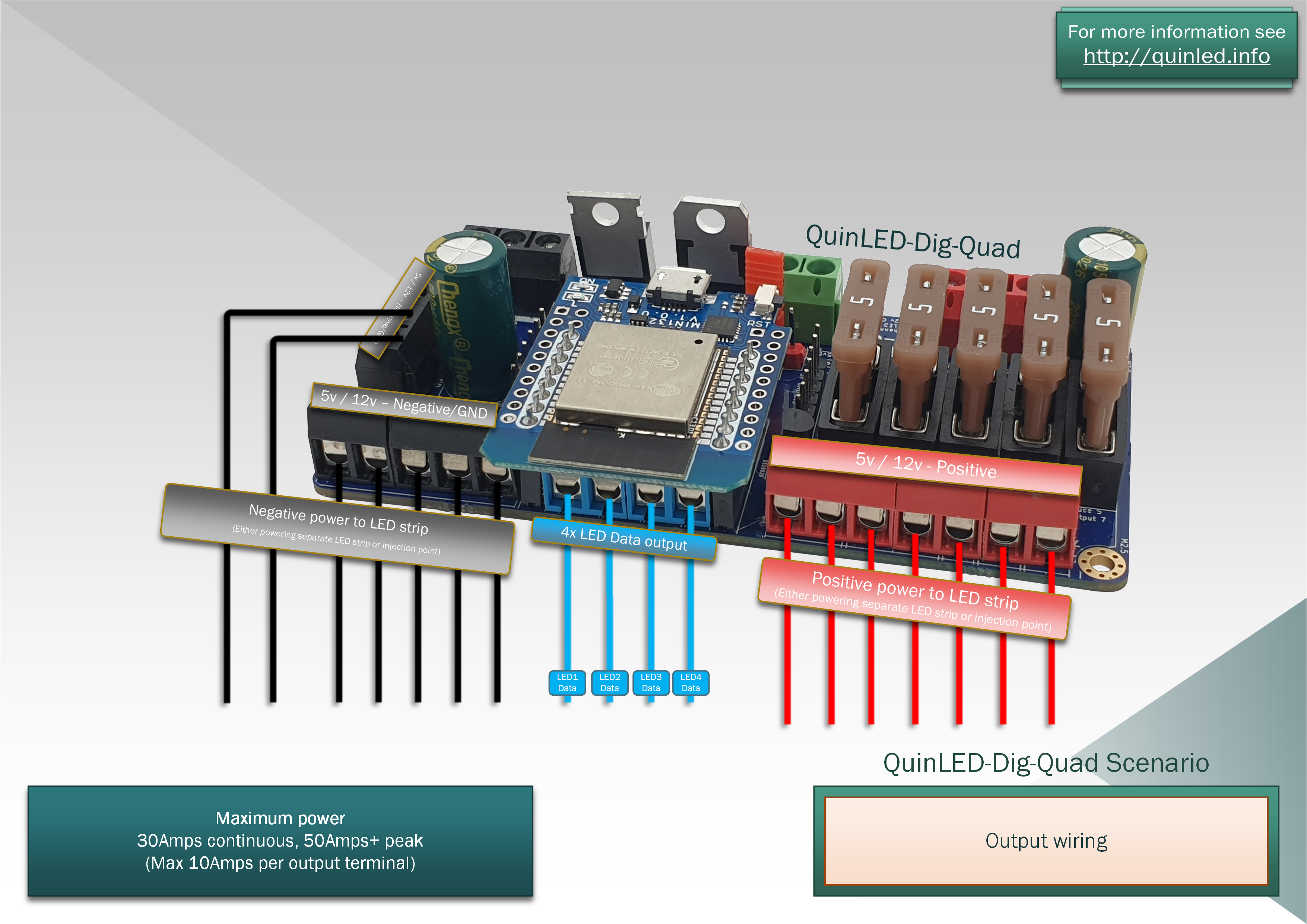
This is a description diagram showing what all output terminals do. Please note that positive terminals 1&2 share Fuse1 and 3&4 share Fuse2, this will make for slightly different fuse calculations.
QuinLED-Dig-Quad wiring Examples
Below are some examples of how to wire up your LED strips including power injection and such. I’ve split it up to 5v and 12v!
In all cases diagrams are designed in regards to 50% usage of Full RGB White for the strips. Please use the power chart to see realistic power usage with which to calculate cable thickness required, also see this live stream running you through the whole process of calculating the wire thickness and everything else.
5v 30LEDs/m wiring examples
5m/16ft | 30LEDs/m | 150LEDs
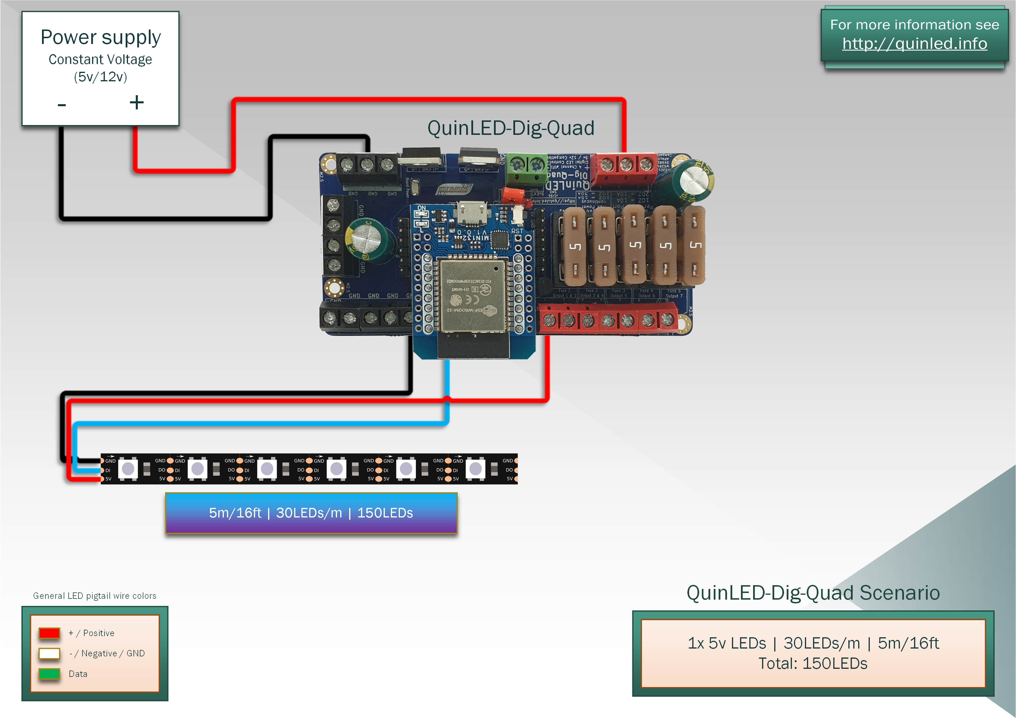
With only 150LEDs in total we can power the LED strip from a single side and there should be no visible brightness difference over the whole strip.
10m/32ft | 30LEDs/m | 300LEDs
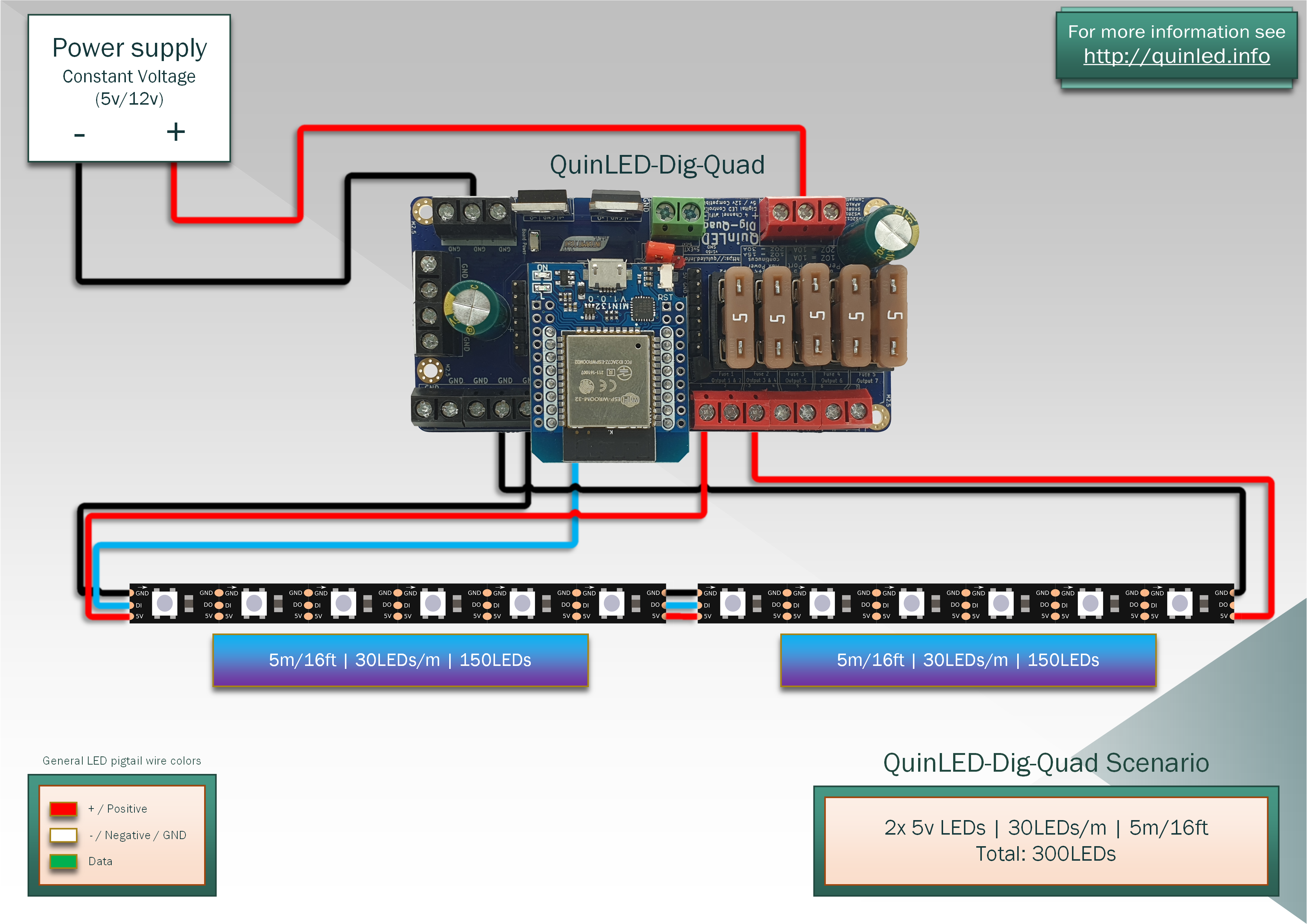
Running 300LEDs in total means we need a second power injection or brightness difference will be visible on the strip running dual colors or RGB white at high intensity.
5v 60LEDs/m wiring examples
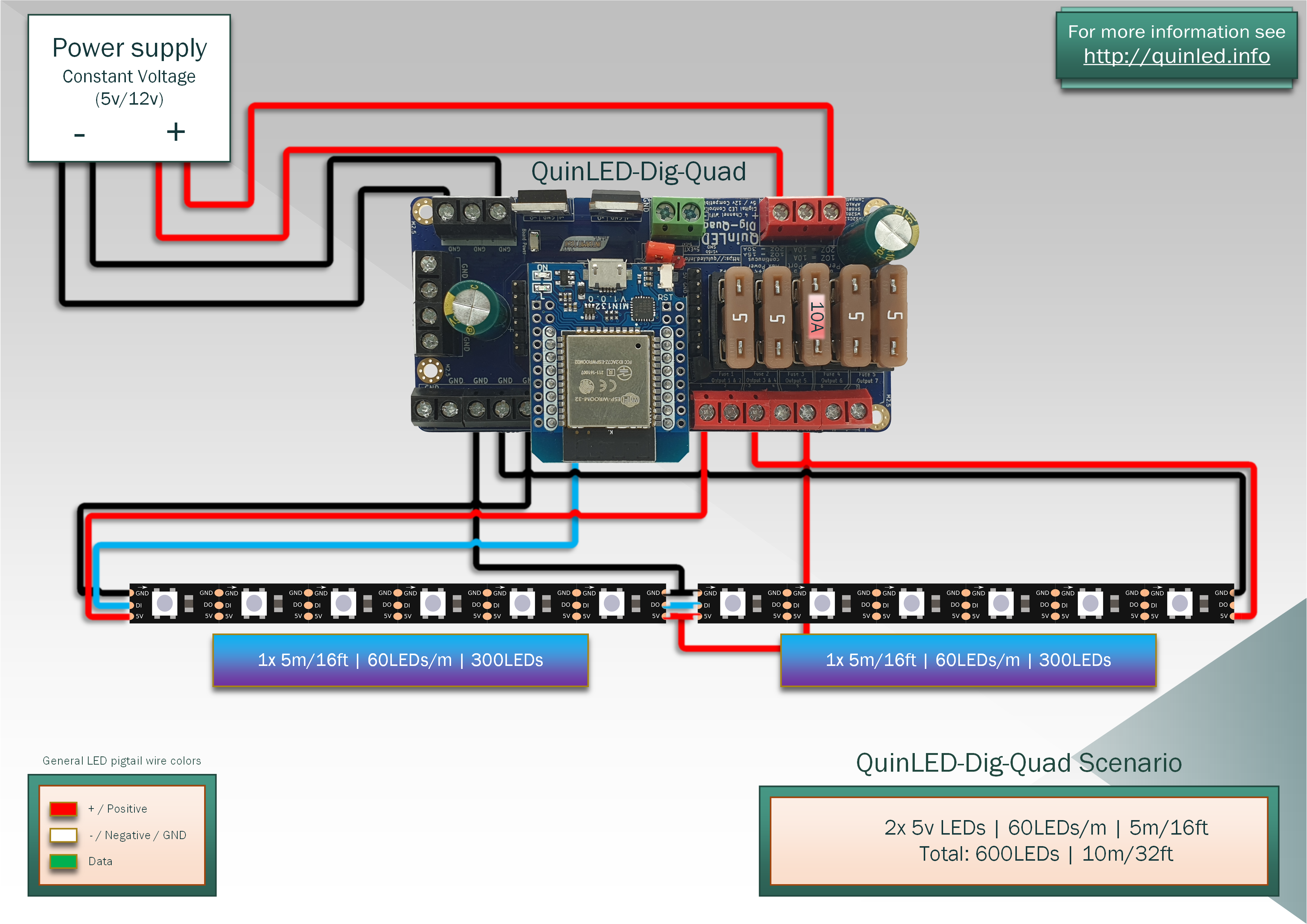
5m/16ft | 60LEDs/m | 300LEDs
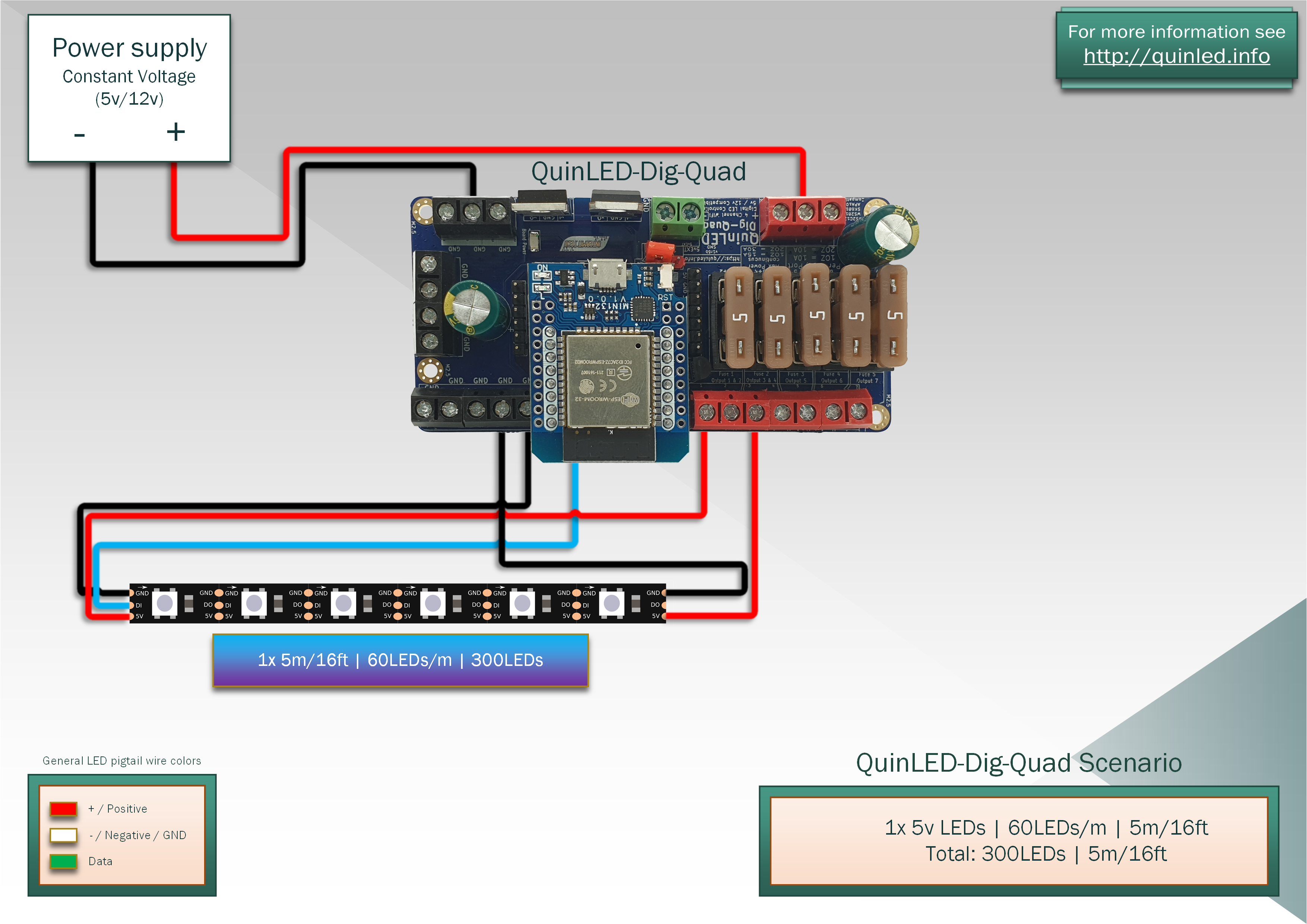
Again, running 300LEDs means we need 2 injection points so even though this is “just” 5m/16ft of LED strip, to be able to run dual colors and white at maximum brightness you need to front + end inject the LED strip.
5v 60LEDs/m wiring examples
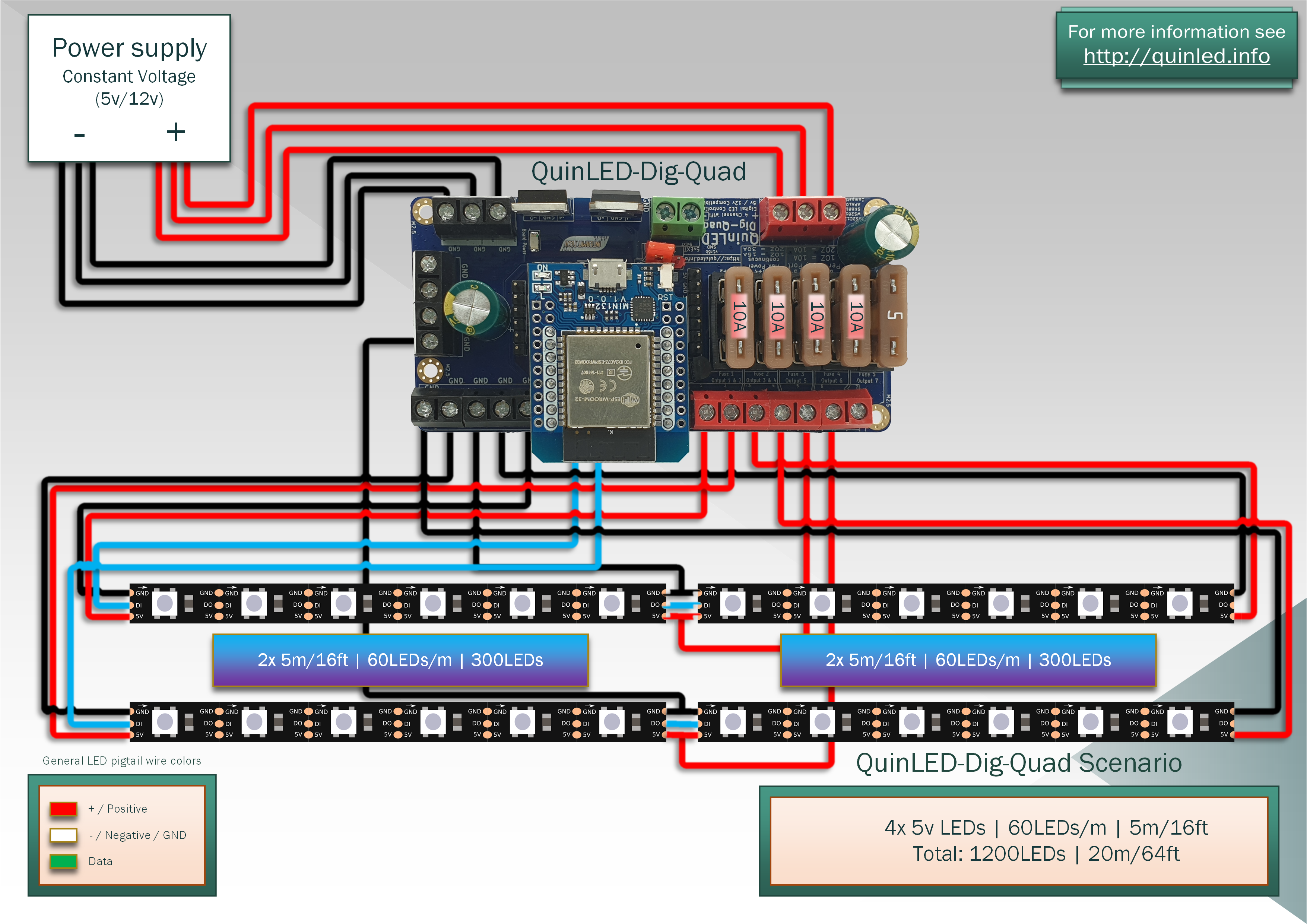
10m/32ft | 60LEDs/m | 600LEDs
 Running 600LEDs we scale up to 3 outputs. We use output 1, 3 and 5. This is because terminals 1&2 share a fuse and 3&4 share a fuse, if we don’t need them yet, better to use individual fuses.
Also note that output terminal 5 has the fuse replaced with a 10Amp fuse. The reasoning behind this is that the front + end power injections as what I call an “edge” injection and these only have half of the LEDs “close to it” vs the middle injection wire and thus that wire needs a larger fuse. I explain this in a bit more detail in my livestream here, it’s a bit long but it does run you through calculating your own LED setup!
You can also see that once we start using more power it’s recommended to connect multiple positive and negative input wires to the QuinLED-Dig-Quad. Please try to keep those wire lengths the exact same length as much as possible.
5v 60LEDs/m wiring examples
20m/64ft | 60LEDs/m | 1200LEDs
 Scaling it even further we see a lot more complex diagram! If you are looking at a setup like this 12v might be a good consideration. Not saying it’s impossible with 5v, but it’s a bit complex wiring wise! Please note the locations of the positive wires where all edge connections are connected to the “shared fuse” positive terminals. That’s because the middle injections already come close to the 10Amp per wire and thus those get their own fuse.
Since this type of setup can use up to 52Amps at full white (considering ws2812b from my power tables) (not recommended for continuous output, ok for peaks, 30Amp continuous max recommended) we need the extra wires to transport all the current.
*If using SK6812 RGBW, you can use less LEDs per data output then with RGB LEDs, please see here for a more detailed explenation.
12v wiring examples
12v 60/96LEDs/m wiring examples
10m/32ft | 60/96LEDs/m | 600/960LEDs
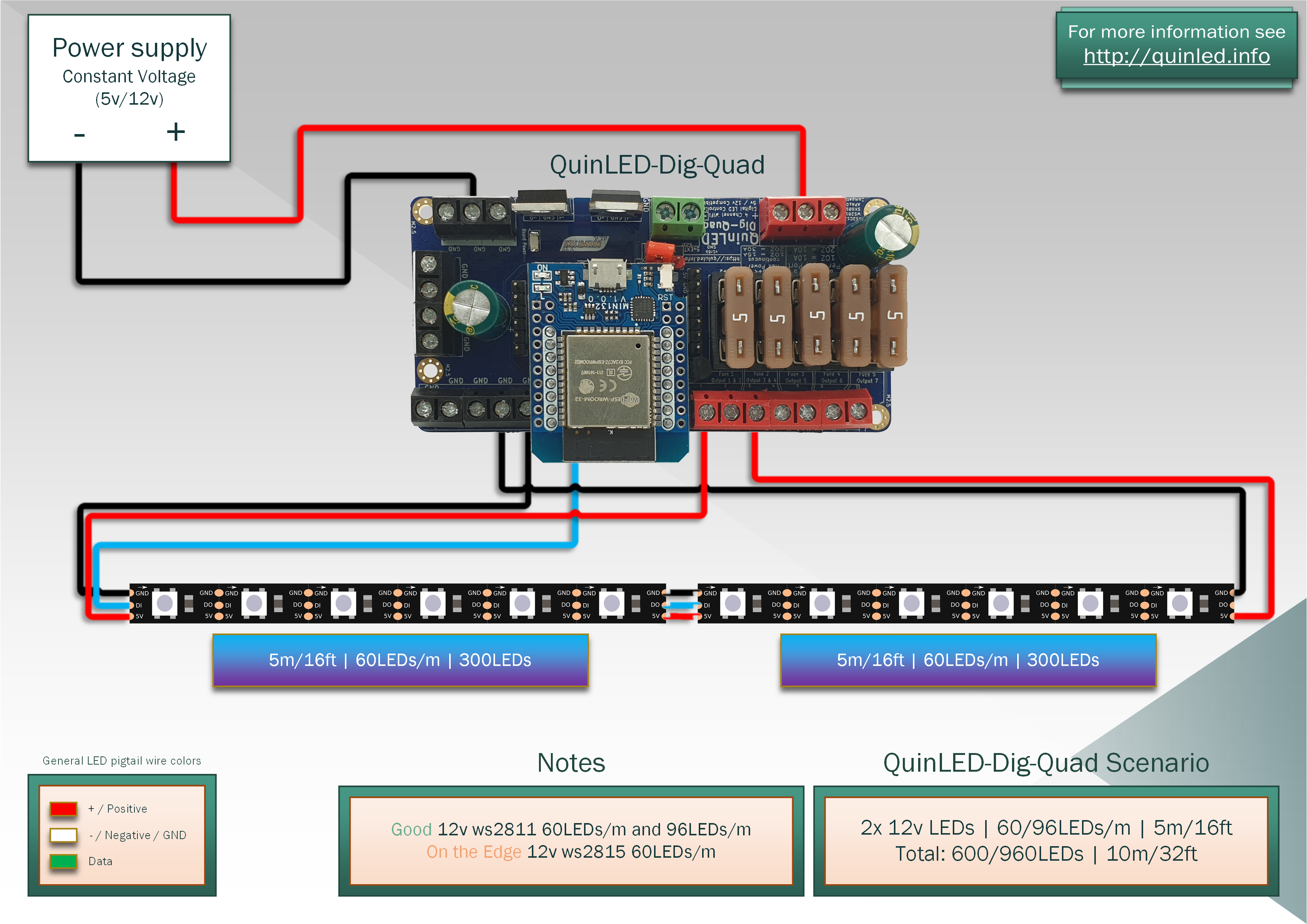 Having the LED strips run at 12v means we can accept more drop (same 10%, but 10% of 12v = 1,2v) and we can do 10m stretches without a visible drop with single colors or effects. Even full white is ok in most situations!
All 12v LED strips except ws2815 run per 3 LEDs. Ws2815 is per 1 LED but has other down sides (being very inefficient). Please see the effect on the power charts closely!
12v 60/96LEDs/m wiring examples
20m/64ft | 60/96LEDs/m | 1200/1920LEDs
 Running 20m/64ft is much easier with 12v again then 5v. Next to having less injection cables, each cable can be thinner since less Amps have to travel over it!
Here we also see another difference, since ws2811 is per 3 addressable, even with 1920LEDs that’s only 640 addressable zones so right on the edge for a single data port. With single addressable ws2815 we have 1200LEDs and addressable by themselves so you need 2 data ports minimum!