
WLED 0.12
What do I configure for QuinLED
![]() WLED 0.13.1 is already available too, functionality and configuration stays the same!
WLED 0.13.1 is already available too, functionality and configuration stays the same!
WLED 0.12.0 was released today and with it comes full multi-channel LED strip support and in GUI configurable pinout! This makes it so that most users will never have to do a custom compile again and that any board configuration out there should be easily configured in the GUI! This is for the LED channels your board may have but also extra features such as a button, etc.!
But how does this work and what pins are needed for the various boards? This article will try and guide you through it so that you can get any QuinLED board (QuinLED-Dig-Uno, QuinLED-Dig-Quad | QuinLED-Quad, QuinLED-Deca) running with WLED easily and quickly!
p.s. This guide will be mainly focused on the QuinLED line of boards but should still also be generally applicable to other setups!
Article Index
Quickly go to the section you are looking for!
Video(s) to go with article
I go through all steps of configuring using this article in this video, easy to follow along!
2022 update video!
Basic install/update steps
1. Download Binary
The first thing to choose if you have a board with Ethernet or without. To support this there are 2 different binaries you can download. But since the QuinLED-ESP32-ABE (Antenna Board Ethernet) isn’t out yet (coming soon!), I’ll do a dedicated article/video about that in the future.
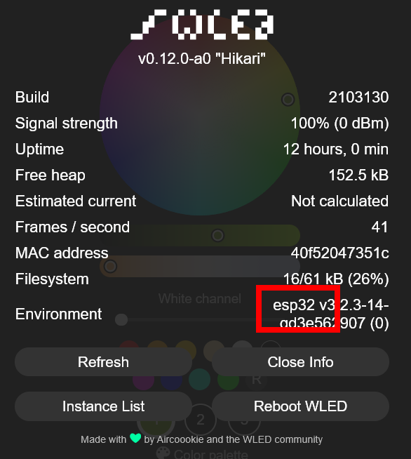
For now we’re going to use the binary without Ethernet support added. There are no more firmware’s with pin names listed in them, you can find all the current binaries here: WLED Github . Please check in the WLED “info” screen if you are running a ESP8266 or ESP32 or make use of the overview below.
Board firmware you likely need
Digitally addressable Controllers
- Pre-Assembled QuinLED-Dig-Uno v2 (current DIY)
- The standard option was an ESP8266
- Pre-Assembled QuinLED-Dig-Uno v3 (current Pre-Assembled)
- The standard option is now always an ESP32
- Pre-Assembled QuinLED-Dig-Quad v1 (current DIY)
- The standard option was an ESP32
- Pre-Assembled QuinLED-Dig-Quad v2/3 (current Pre-Assembled)
- The standard option was an ESP32
For any DIY Digitally Addressable board it’s whatever your paired up with it!
Analog Controllers
- DIY QuinLED-Quad
- Always has an ESP32
- DIY QuinLED-Deca
- Always has an ESP32
[IMAGE OF BIN TO DOWNLOAD]
2a. Flash using ESPhome-Flasher to Flash using USB
Currently below is “old” information (except for driver install), after installing drivers use https://install.wled.me in a Chrome browser to flash your ESP directly!
This method erases any settings, presets, etc.
My preferred method of flashing boards is using ESPhome-Flasher since it’s easy to use, you can download that tool here. Alternative methods to flash the firmware can be found here. For ESPhome-flasher, after the download no install is needed, just start it after downloading!
Remove the ESP8266/ESP32 module from your QuinLED board and plug it into a USB port on your computer. Most often your computer will already have a driver for the USB-to-Serial chip used, if not, depending on the board it might be this one “CH340” or “CP2012“.
If all is correct and you’ve started ESPhome-Flasher with the ESP8266/ESP32 connected to your computer you should see the following screen and be able to select a serial port:

Browse to the firmware image you downloaded for your board (Either ESP8266 or ESP32) and then just hit flash!
— Do not hit “view logs” before trying to flash, it will give you an access denied error while trying to flash. Close and re-open the program!

Flashing is progressing normally, you should see text move over the screen for a bit.
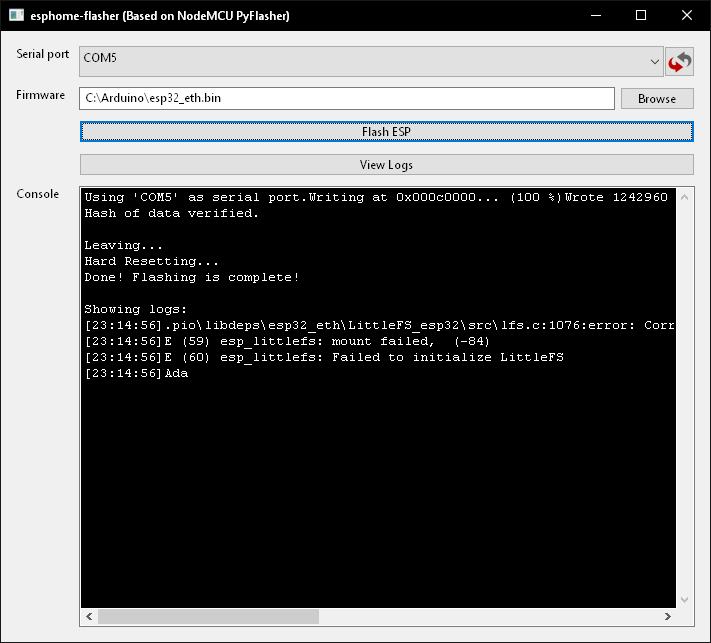
And flashing is done!
Setup WiFi after USB flash
After this step, since all configuration data was erased, you will have to fill in your WiFi credentials again by joining the “WLED-AP” WiFi Network (password “wled1234”). If you’d like to see how to do that, please watch this part of this slightly older video:
2b. Flash using WLED OTA (Over The Air)
This method preserves current settings, presets, etc.
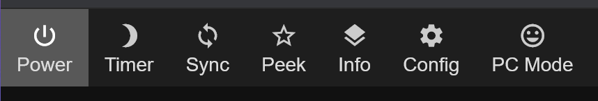
Open WLED either using the WLED mobile client or in a web page and go to “config”:
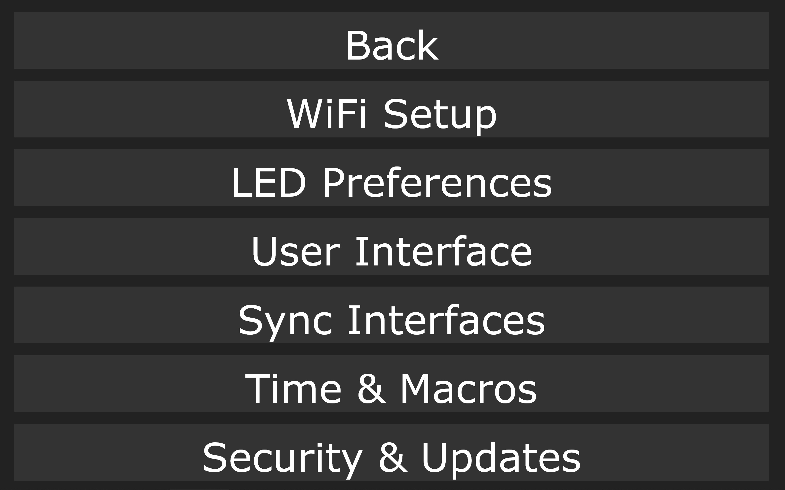
There open the last entry called “Security & Updates”:
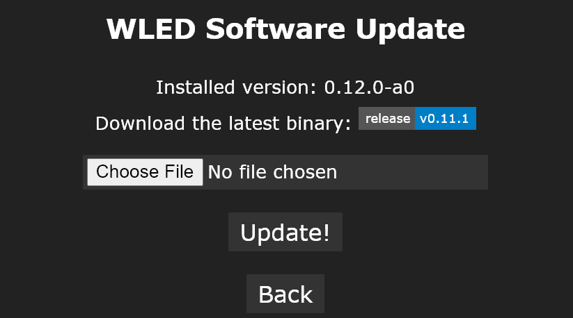
Once there click the “Manual OTA Update” button:
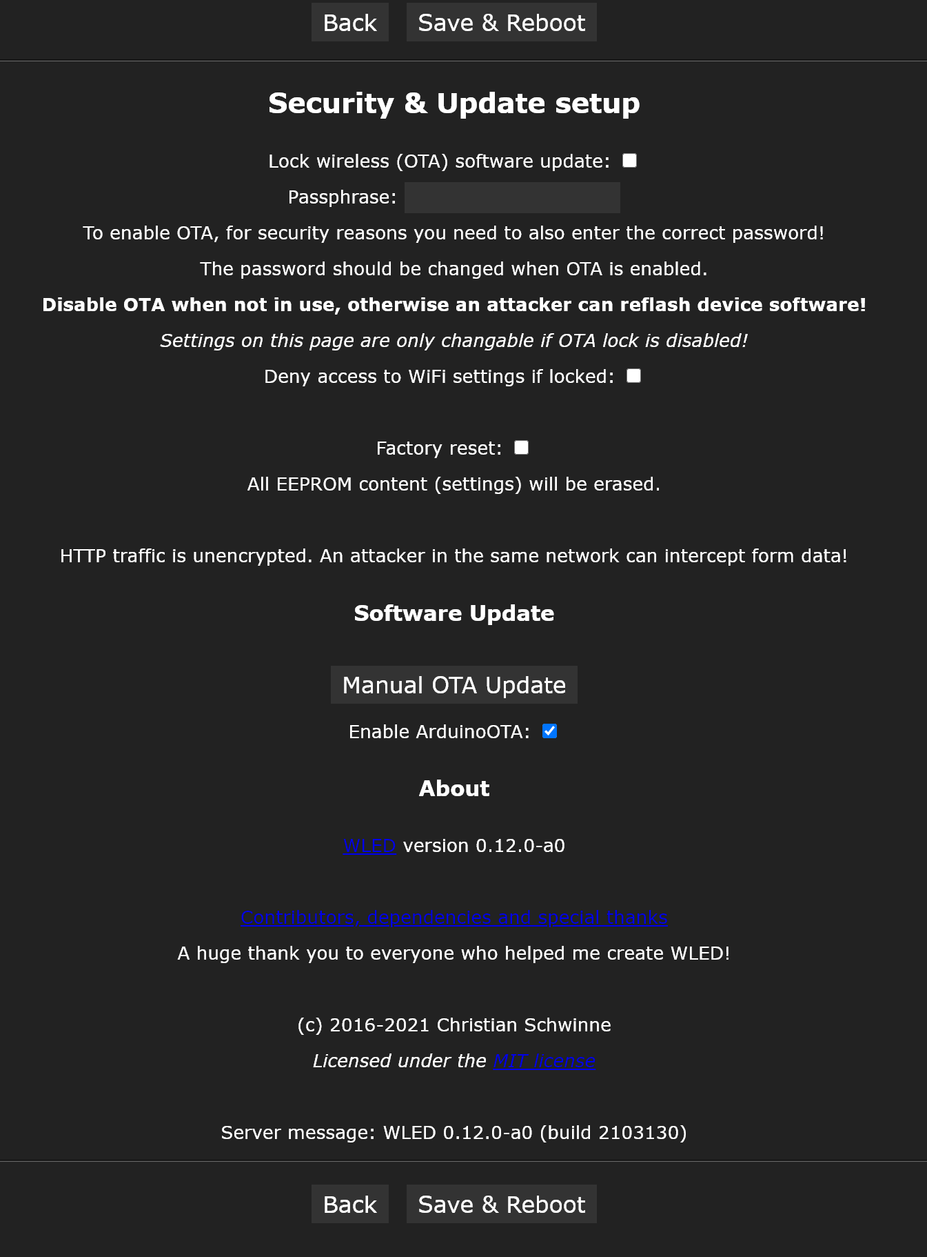
And there hit “choose file” and select the .BIN image you downloaded form the WLED Github, hit “Update!” and after a little while WLED should come back running the same version!
Configure LED pins
If you flashed WLED over USB it will come up with a completely default configuration, depending on the board and ESP combination you are running that means you might already see LEDs burning orange, or not. If you flashed using OTA most likely all settings where preserved and everything should function as you where used to before updating.
This guide is going to assume a “clean” install!
WARNING: Do not mix 5v and 12v LEDs on a single board!
How to configure LED pins
In the main interface go to the “config” menu and select “LED preferences”:
For now we’re only going to focus on this part:
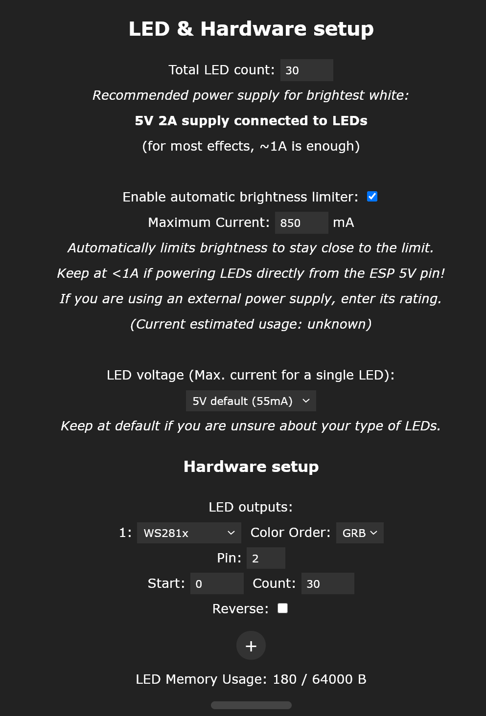
In the above image you can see the default which which are “30” “WS281x” LEDs configured on pin “2”. Also the brightness limiter is enabled, in the rest of my examples I’ll have it disabled to get a more compact screenshot, please use the configuration values suitable for your setup!
What pins do you need for your board?
The pins you need for your board and combination are listed on the “pinout” page per board, but below I will post a quick summary for the current digital boards too.
Check on the board which version you have to use the right pins!
Official pinout pages:
- QuinLED-Dig-Uno pinout page (updated for new pre-assembled v3 version!)
- QuinLED-Dig-Quad pinout page (updated for the new pre-assembled v2/v3 version!)
- QuinLED-Quad pinout page
- QuinLED-Deca pinout page
Quick pinout summary for current Digital boards
QuinLED-Dig-Uno v2 with ESP8266
L1_D = pin 2
L1_C = pin 1
QuinLED-Dig-Uno v2 with ESP32
L1_D = pin 16
L1_C = pin 1 or 3 (depends on ESP32 board used)
QuinLED-Dig-Quad v1 with ESP32
LED1 = pin 16
LED2 = pin 3 / 1 (depends on ESP32 board used)
LED3 = pin 1 / 3 (depends on ESP32 board used)
LED4 = pin 26
Generic/Other board
If you are not (yet) running a QuinLED board, check here for general pin recommendations from the WLED wiki.
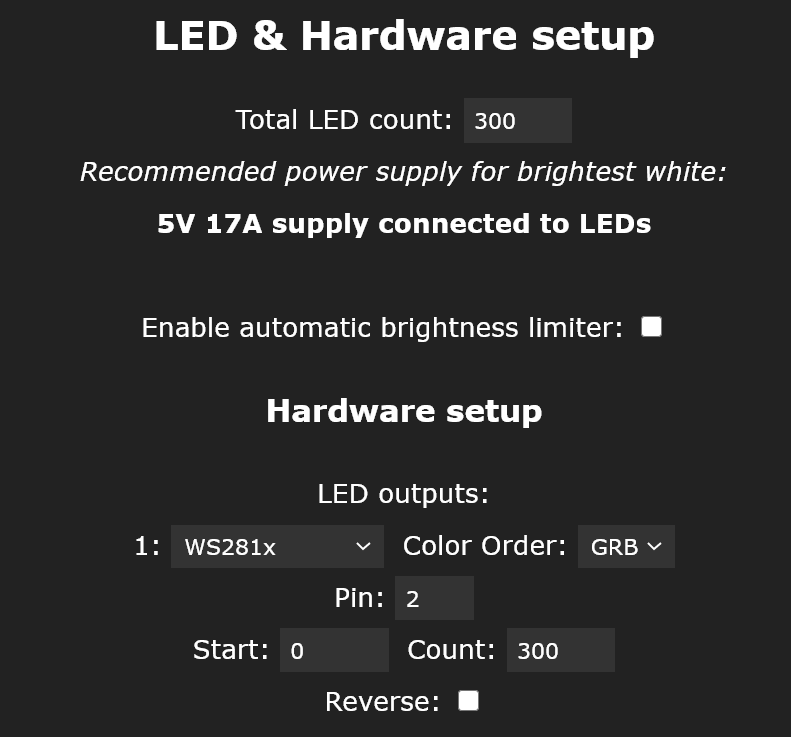
Configuration example 1
QuinLED-Dig-Uno v2 with ESP8266 and 5m/16ft of 60LEDs/m (3oo LEDs total) connected to L1_D
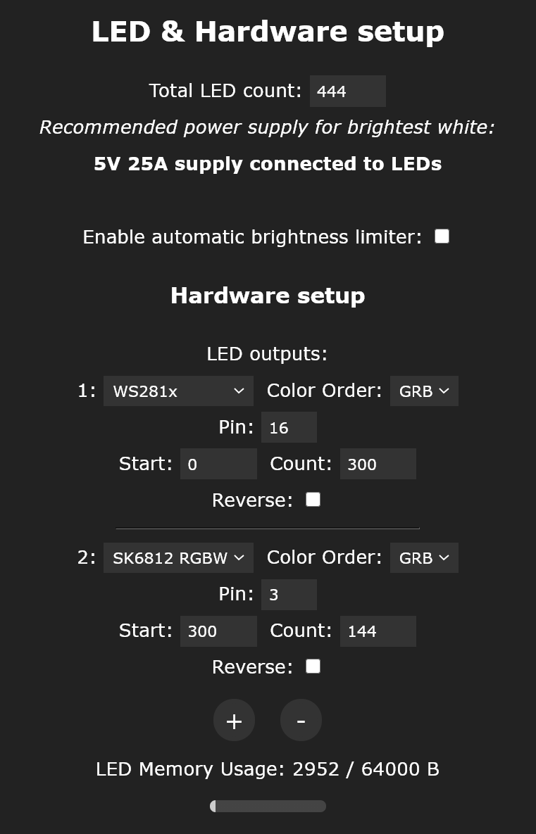
Configuration example 2
QuinLED-Dig-Uno v2 with ESP32 and 5m/16ft of 60LEDs/m (3oo LEDs total) on L1_D + 144LEDs SK6812 on second data port L1_C
- Total count is 300 + 144, so all LED channels combined
- All LEDs are internally one giant LED strip
- This is why you need to tell it where the second LED strip starts (“start: 300”)
- You can either use it as one big LED strip or cut it up using the Segments feature and control each output separately
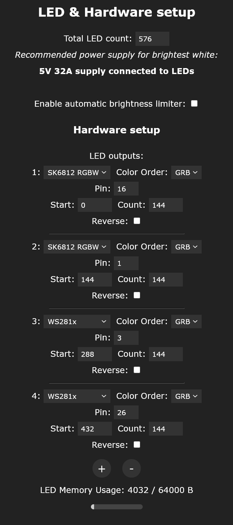
Configuration example 3
QuinLED-Dig-Quad v1 with ESP32 and 4x 144LEDs (one on each data port) (2x SK6812 + 2x ws281x)
- Total count is 144 + 144 + 144 + 144 = 576, so all LED channels combined
- All LEDs are internally one giant LED strip
- This is why you need to tell it where the second LED strip starts (“start: 144”, “288”, “432”)
- You can either use it as one big LED strip or cut it up using the Segments feature and control each output separately
2 more things – End Conclusion
With the above steps you should be able to get a, configured completely from scratch, QuinLED board up and running with the new WLED 0.12.0 version!
Extra pins
Of course this article doesn’t cover everything, for instance, all “extra” pins can now also be configured from the GUI like seen here:

Please look up your board and configuration in the pinout guide for that board and version and you should be able to find the pins you need to set pretty quickly!
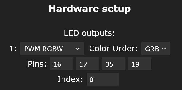
Analog Configuration for QuinLED-Quad
Another option I haven’t highlighted is how to configure WLED to run on one of my Analog boards. It’s pretty simple, select the Analog mode from the drop down menu and configure it again according to the pinout guide, here is an example of a RGBW strip on a QuinLED-Quad (not Dig, the Analog Quad!):
If you have any more questions, the Discord server is the best place to ask!