Why would you want a power supply relay?
Digital LEDs are basically analog LEDs but each LED has a tiny controller inside of them. That means that even when you turn them off each LED will continue using a little bit of power (not the case for pure Analog LEDs like with the QuinLED-Quad or QuinLED-Deca). In large installations this is not desirable and turning the whole board on and off is also a hassle.
The QuinLED-Dig-Uno was designed to be able to use a power supply relay and this can be done in 2 different scenarios. Either by adding a relay behind the output of the QuinLED-Dig-Uno board so in the DC path. Or by using 2 power supplies. One to power the board with 5v and GND and another big power supply (5v or 12v) to provide power for the LEDs that has a relay so it can be switched on and off independently.
For either case WLED has built-in functionality that when powering off the LEDs completely it can trigger a relay to shut off power to the LEDs (or “LED Power Supply”).
Each of the 2 options have their pros and cons:
- Behind the QuinLED-Dig-Uno board cutting the Positive DC line to the LEDs
- Only requires a single power supply
- Slightly easier to wire (no need to mess with AC)
- Relay and traces need to carry a lot of current
- Because of this limited to a much lower Amperage (often limited to max 5A!)
- Less efficient because bulky large power supply is used to supply tiny current
- With a separate “LED Power Supply” connect through a relay to cut the power to the LEDs and using a separate power supply (Like a phone charger) to keep the board awake
- Small power supply more efficient when kept running board only
- Means much lower standby usage because the big power supply is truly off
- Able to switch much higher currents because switching on AC side
- No problem running 20A or 30A 5v/12 DC Power Supplies because AC side Amperage is much lower
- Slightly more difficult cabling (need to mess with AC wires)
- Small power supply more efficient when kept running board only
Wiring Diagram
Separate “BIG” AC power supply
Below is a diagram for hooking up a relay in between the AC power of the big power supply and where you can connect the separate 5v power supply.
(You are feeding 5v directly into the 5v pin, leave the 5v/12v selection jumper off!)
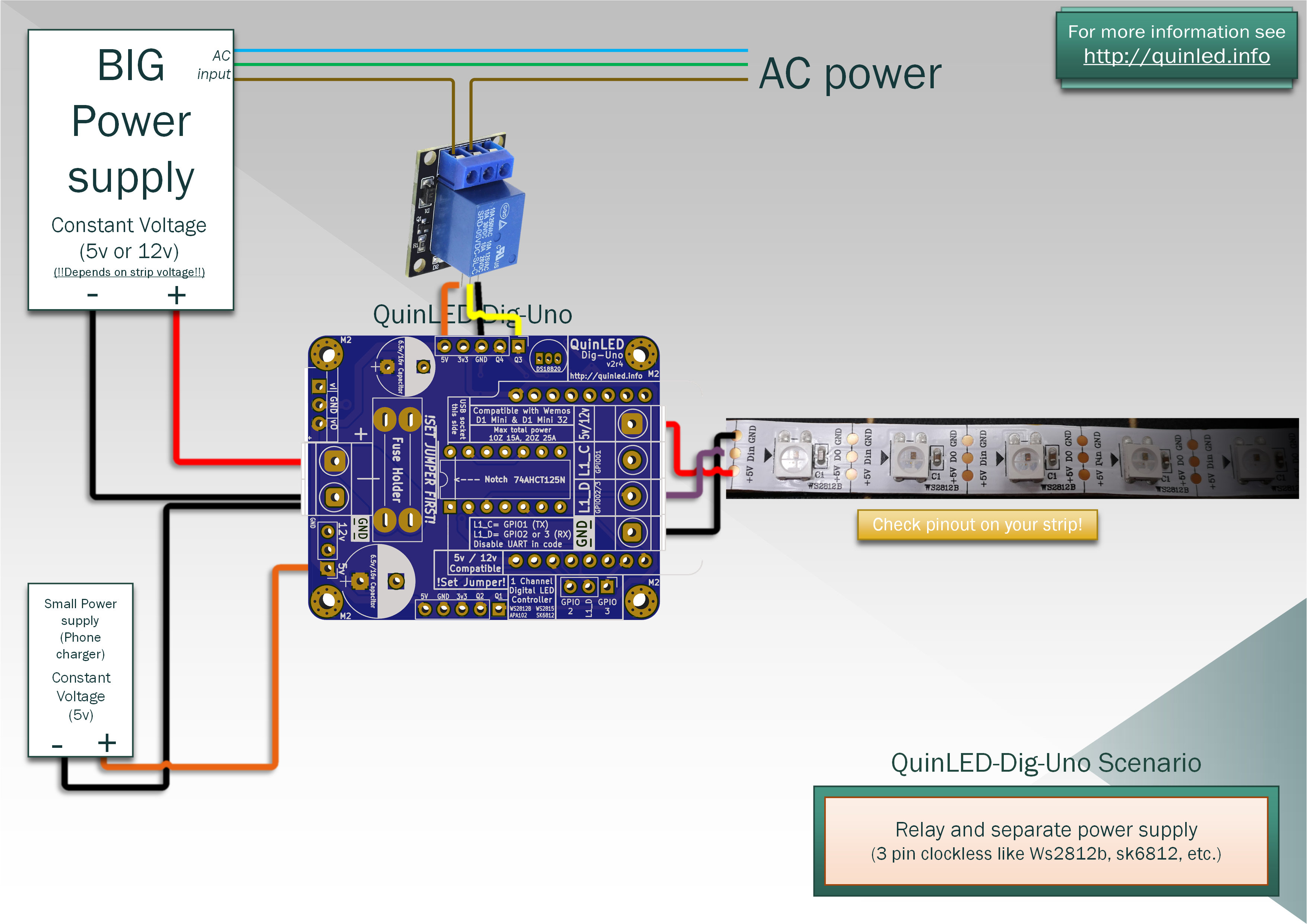
Relay terminals
For WLED usage, connect the AC wires in the relay to the NO and common pin. That means by default the relay is “open” (off) and WLED then pulls it high when the LEDs are turned on which switches the relay to “closed” (on).
DC Relay
There is no diagram for this option because hooking up the Relay is exactly the same, and you just place it in between the path of the Positive (red) output of the board.
More info on Relays
A while back I also did a video about relays, you can find the related article and video here!