QuinLED-Dig-Uno Soldering guide
This guide is for boards v2r5 and lower. Please see revision history for differences and/or newer versions
QuinLED-Dig-Uno v2r6 guide is here
To solder the QuinLED-Dig-Uno together I’ve made a video which takes you through all the steps involved. I think anyone should be able to follow along and basically replicate what I do in the video. Just pause the video at each step and do it yourself. I know soldering seems daunting at first, but with some decent equipment I think anyone should be able to solder a working board together!
Beyond this video I also have the highlight picture guide below, once you are doing watching the video, make sure to check that out also!
Soldering Highlight guide
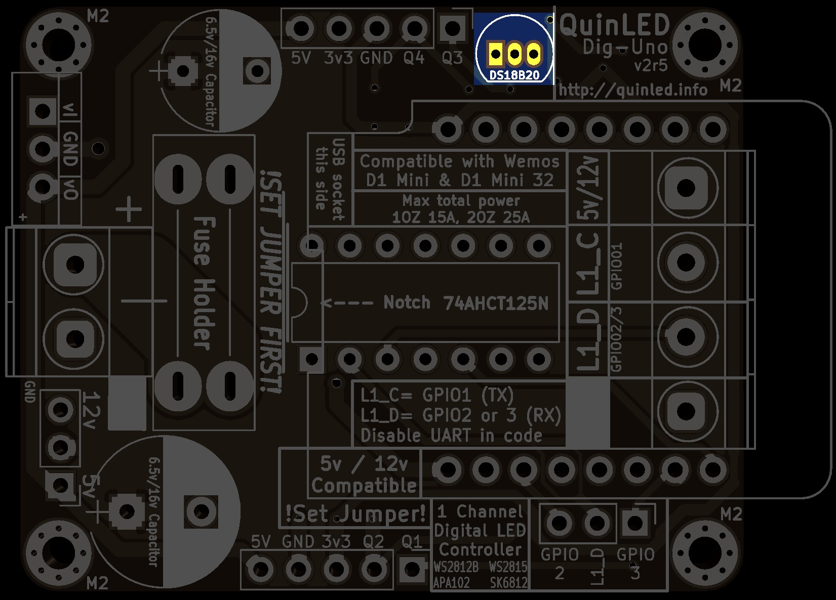
To make soldering even easier I have made some highlighted pictures where you can see exactly where each of the components go per type.
1. SMD Capacitors
4x 0.1 µF
1x 10 µF

2. SMD Resistor
1x 4.7k resistor

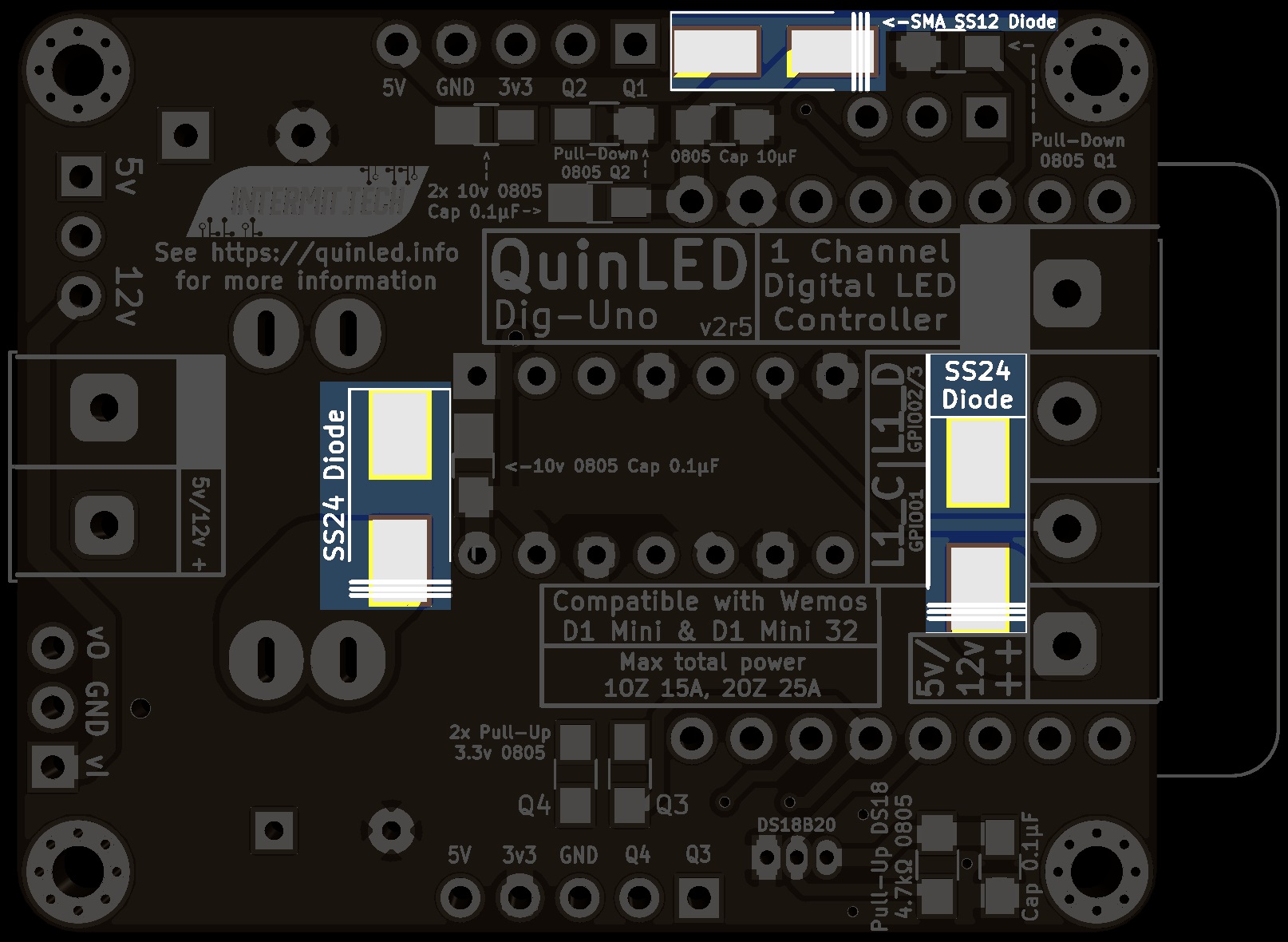
3. SMD diodes
These have polarity, mind the stripe on the board and diodes!
1x SS12 diode
2x SS24 diode
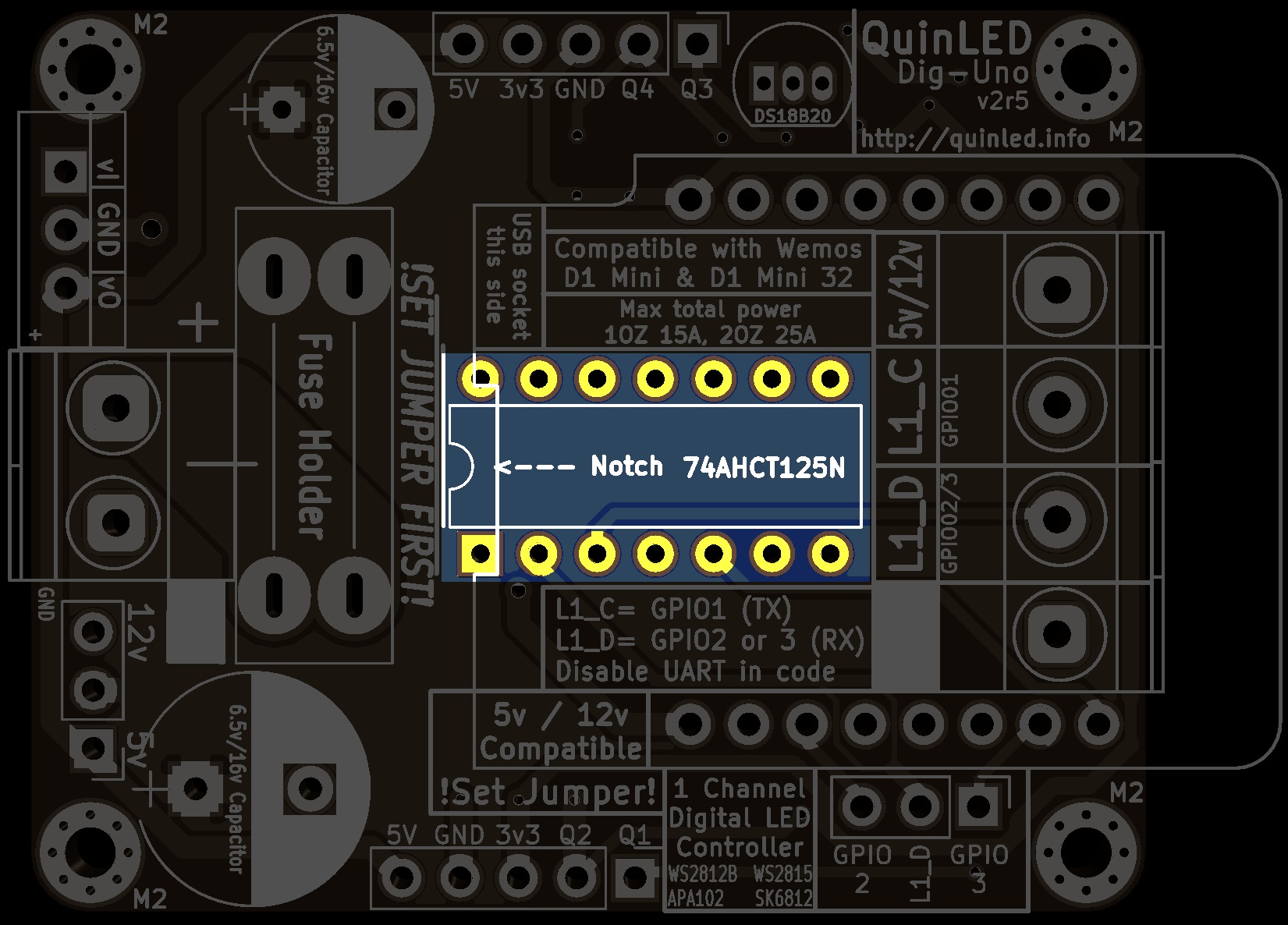
4. Level Shifter
1x 74AHCT125N or 74HCT125N
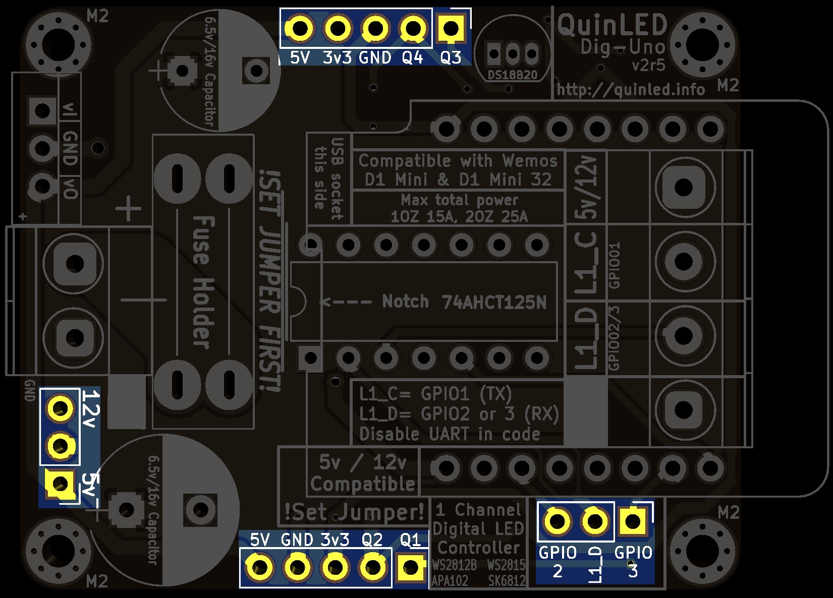
5. Male Pin headers
2x 5 pins
2x 3 pins (red and yellow color)
6. Screw Terminals
1x 2 times terminal (black)
1x 4 times terminal (blue)
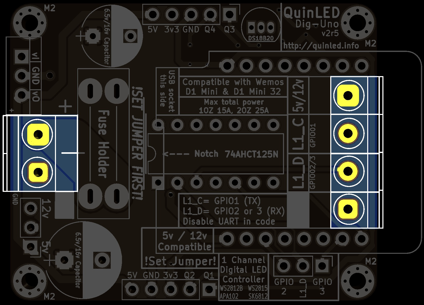
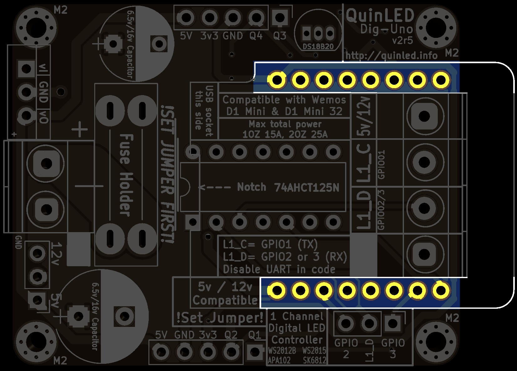
7. Female headers + Micro-controller
Set of 2x 8 pin female headers + 2x 8 pin male headers to solder onto the micro-controller
Easiest way to solder these is by making a little “sandwich” like I show in the video!
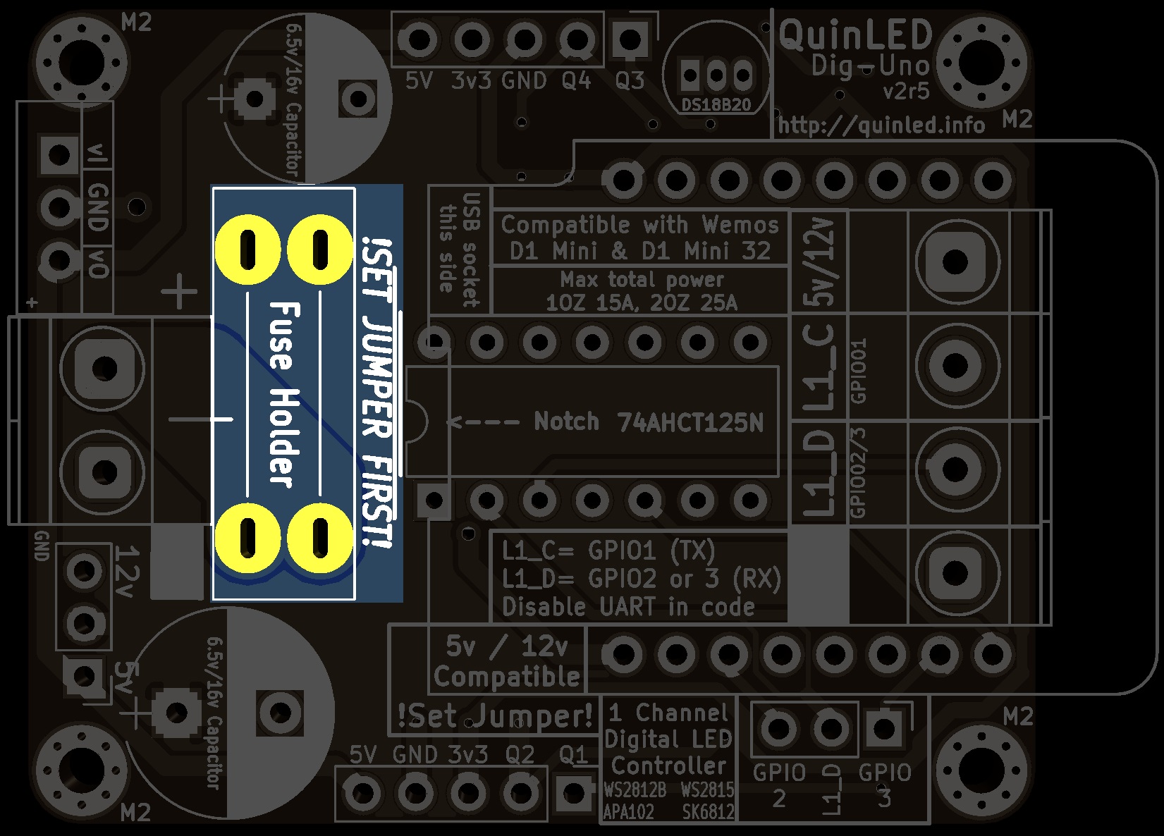
8. Fuse holder
Single fuse holder
9. Through-Hole capacitors
1x 8mm x max 8mm height
1x 10mm x unlimited height

10. Optional DC-DC converter
1x DC-DC converter (line up vi and vo)
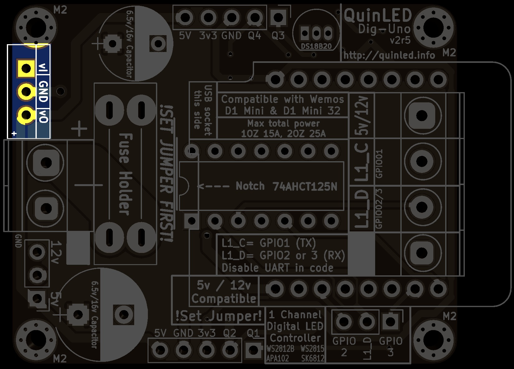
11. Optional DS18B20 temperature sensor
1x DS18B20 temperature sensor
Ending remarks
Did all of the above? Great, you’re done, go on to either the wiring guide or one of the programming guides from the front page.