QuinLED-Dig-Uno Hardware guide
This hardware guide is for board revision v2r5, current version is higher, please see the revision page for updates.
Please see Dig-Uno Index for newest articles
To build the QuinLED-Dig-Uno you are going to need several components which are listed below. As a little disclaimer, please take a look at this article about my shopping links. After reading that, make sure to also take a look at the additional hardware and tools you might need to be able to complete this project. Then I also have articles about 5v and 12v addressable LED strip and the differences of them and even an article about different addressable LEDs chips you can buy!
Those articles are a lot of information but will teach you everything you need to know! If you have any questions about the components, let me know in the comments!
Total costs for a single board
What a single fully built QuinLED-Dig-Uno board will cost is a bit harder to determine then my other boards because you have several options. Those options are to make the board only 5v compatible or 5v and 12v (requires extra components). The second choice is if you are going to use an ESP8266 or a ESP32.
These per board values are a bit skewed because it’s calculated using bulk bought components, buying minimum quantities of all the components will make it a bit more expensive per board
The base board with only 5v compatibility will cost you about 8$, adding 12v compatibility to that will cost you an additional 3$. So that raises the total cost from 8$ to 11$. Then you can use an ESP8266 or ESP32. An ESP8266 (Wemos D1 Mini) will cost you about 2$ if you’d rather run an ESP32 this will cost you about 6,5$ to 7$.
So the cheapest would be a 5v only board with an ESP8266 on it and that would cost you only 10$. The other side of the spectrum is a 12v compatible board with an ESP32, this will set you back 18$ per complete board.
Board Summary
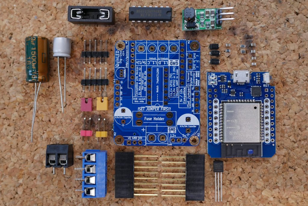
You need the following components and quantities:
Components needed
Most components come in multiples of 5 or 10. I will try to link to several batch sizes available so you don’t immediately have to buy the amount for 10 or more boards. Of course, if you do, the per board the price becomes (much) cheaper! Also when buying larger amounts of components you slowly but surely amass common components used in hardware tinkering which are convenient to have lying around!
All amounts of the components will be listed in green text. The amount listed there is for building a single board!
![]()
QuinLED-Dig-Uno PCB boards
- 1x QuinLED-Dig-Uno PCB
I always order my boards from dirtypcbs.com and they haven’t failed me yet. If you order a protopack you get anywhere from 10 to 12 boards and all of those should work perfectly. If you include shipping, their prices are very competitive! But because of popular demand I have now also included a link to PCBway, their ePacket shipping can sometimes be cheaper and quicker then what DirtyPCBs offers but it differs per country and location, check what works best for you:
Slow shipping is SLOW (sometimes 8+ weeks). PCBway e-packet is a good compromise between decent time and money
![]() DirtyPCB QuinLED-Dig-Uno_v2r5
DirtyPCB QuinLED-Dig-Uno_v2r5
![]() PCBway QuinLED-Dig-Uno_v2r5
PCBway QuinLED-Dig-Uno_v2r5
— If you do not have a PCBway account yet, consider creating one using this affiliate link! 🙂 After creating come back to this page and use order link above.
Merged boards
This above links are for ordering 5x5cm boards of just the QuinLED-Dig-Uno which will yield you 10 to 12 functional boards (select 10 using PCBway). If you would like to order more than one of my designs check my separate page where you can buy combined versions with different designs on one PCB if you want to buy multiple QuinLED’s this can save you a lot in PCB and shipping costs!
Gerber files?
I do not have the gerber files available. I might release these in the future so you can use your own favorite board house but in the past I’ve had issues where people would keep using (and spread) old versions because that’s what they downloaded at some point in time. Also there were complications where certain board houses did things differently then I expect them to do. That complicates things such as optimizing and improving the design over time, hopefully you can understand.
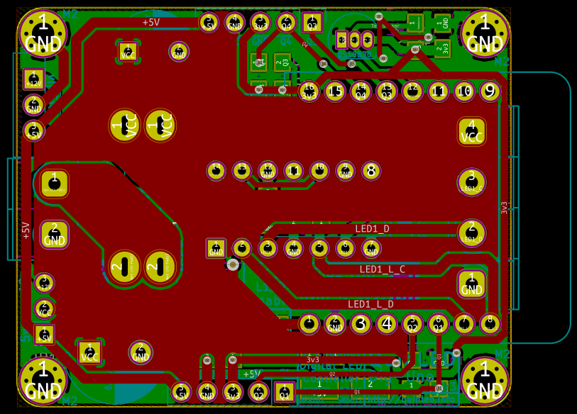
Board size (without ESP) is 5cm by 4cm
![]()
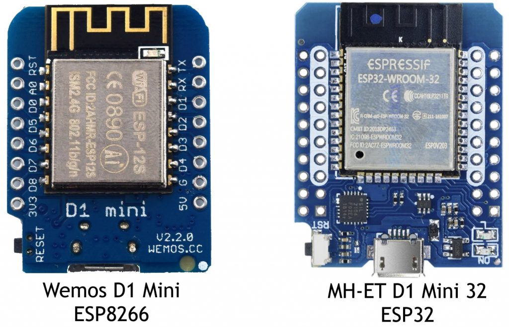
Wemos D1 Mini (ESP8266) and/or Wemos D32 Mini (ESP32)
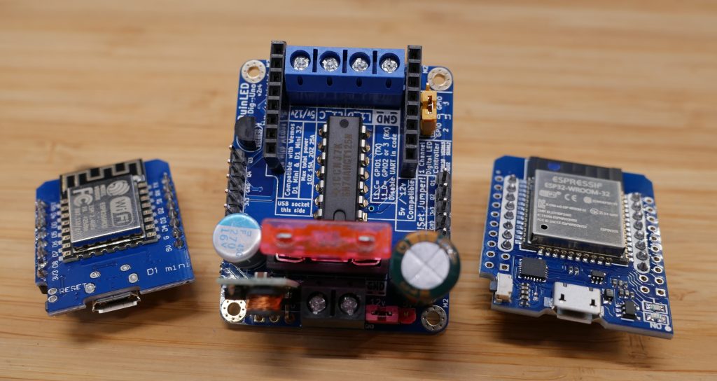
The main brains for the QuinLED-Dig-Uno can be the Wemos D1 Mini which is an ESP8266 based board or the Wemos D32 Mini which is an ESP32, the PCB has been designed in such a way that you can literally swap them! The main advantage of the ESP32 is that it’s a lot faster so it can handle more LEDs or sensors connected to it using the GPIO pins.
A secret bonus feature is that while this board is called QuinLED-Dig-Uno, if you use clockless (only one (data) pin like ws2812b) LED strip you can actually hook up two at the same time and drive both separately! The ESP8266 just doesn’t have the horse power to do that. For more differences check out the board info page.
*These wemos boards are different then the MH-ET Live ESP32 boards I usually use, my other designs will still use that one though!
- 1x Wemos D1 Mini (ESP8266)
and / or
- 1x Wemos D32 Mini (ESP32)
![]()
Female headers
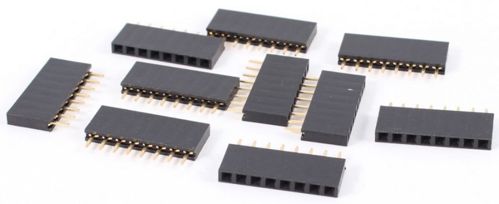
In theory you don’t need to buy these because they should come with your Wemos D1 Mini or Wemos D32 Mini. If they didn’t you need 2x 8 pins female headers.
*Some Mini 32 kits come with 10 pin short headers, but do have 8 pin long headers in the package, these can be harder to solder though so maybe pick up some extra
- 2x 8 pins 2.54mm female header
![]() 10 pcs 8 pin 2.54mm female headers
10 pcs 8 pin 2.54mm female headers
Screw terminals
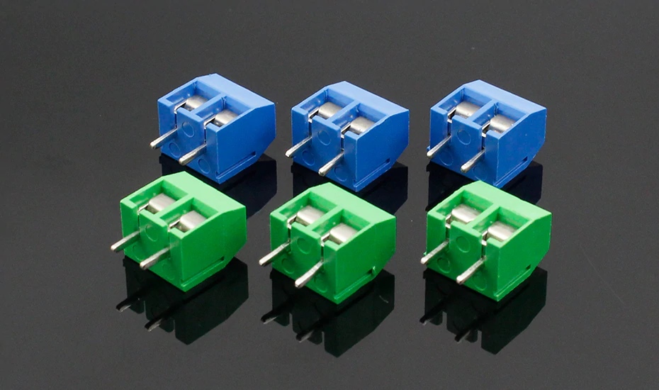
To secure all the wires to the board you are going to need several screw terminals. I personally use different colors for input and output but buying multiple colors does make it more expensive (buying multiple colors gets you a lot of terminals in stock 😉 ).
- Per QuinLED-Dig-Uno you need
- 1x 2 port Board power input terminal
- 1x 4 port LED output terminal
So that makes 2x terminal input blocks in total (The power block has 2 inputs, the LED block has 4 inputs!)
Board power input
For voltage input I like to use 2 Pin Black terminals
![]() 10 Pcs 2 pin BLACK 5.0mm Screw Terminal
10 Pcs 2 pin BLACK 5.0mm Screw Terminal
![]() 100 Pcs 2 pin BLACK 5.0mm Screw Terminal
100 Pcs 2 pin BLACK 5.0mm Screw Terminal
Dimming channel output
For the LED Data and LED Clock channel outputs I like to use blue terminals because it’s more alike to GPIO. With that said, the board + and – output terminals are on the same block! You need 1x 4 pin terminal.
![]()
10 Pcs Blue 4 pin screw terminals
![]()
100 Pcs Blue 4 pin screw terminals
2.54mm Male pin headers
For the GPIO pins you need to get 2x 5 pin single row of male through hole pin headers. The pins come on a strip and you can buy a strip of 40 and just snip off the length you need.
- 2x 5 pin single row 2.54mm male pin headers (GPIO headers)
- 2x 3 pin single row 2.54mm male pin headers (5v/12v voltage select)(Also needed on 5v only version!)
Different colors
If you’ve seen my example boards you probably noticed I make one of the 3 pins in red and the other in yellow. The reason I do this is because one of those determines the voltage the board runs at, setting it wrong can damage the onboard equipment so using a different color for it can help remind me to check it!
I recommend getting a kit of colored pin headers + jumpers using the link below!
![]()
Set of Colored pin headers + Jumpers (Amazon link without jumpers!)
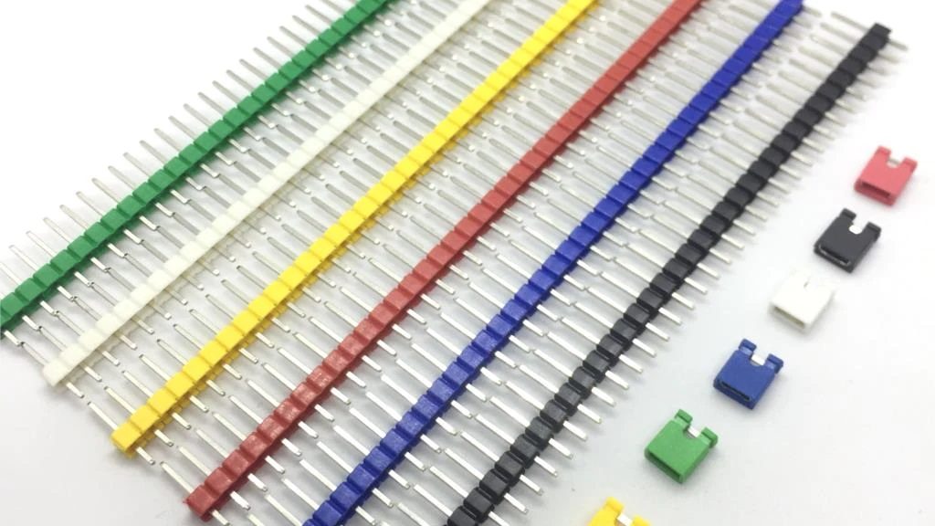
Jumpers
!If you bought the above pin header kit from Aliexpress you do not need seperate jumpers!
To be able to set the voltage of the board to 5v or 12v you are going to need a little jumper, the GPIO selection is also done using a jumper. To make them standout I recommend getting a kit with several different colors. On my boards I use red for the voltage select and yellow for the GPIO select.
- 2x 2.54mm Jumper (Red & Yellow)
![]()

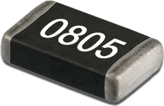
0805 Resistors
Depending on what parts you are going to use on the board you might need some resistors:
- 1x 0805 4.7k Ohm resistor (For Dalles Temperature Sensor, you can leave it off if you don’t use it)
- 4x 0805 10k Ohm resistor (For 2x Pull-Up and 2x Pull-Down pads for Q1,Q2,Q3 and Q4 GPIO pins, you can leave them off if you don’t use them)
*You will need a tweezer to put these into place, make sure to check out the tools section!
![]() 100 Pcs 0805 resistor (Has both 4.7k and 10k available)
100 Pcs 0805 resistor (Has both 4.7k and 10k available)
(Optional 0805 Resistor book)
Optionally you could also choose to buy an 0805 resistor book. This booklet comes with lots of different values included, check it out over here.
0805 Capacitors
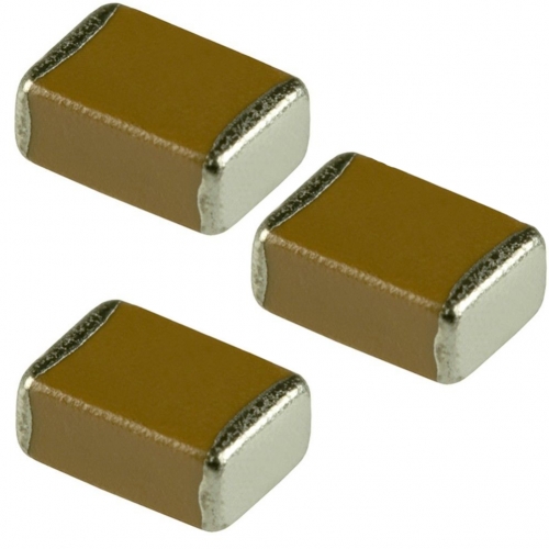
To stabilize power delivery to all components a few capacitors are needed. For space saving and ease of soldering we’re using 0805 size capacitors.
- 4x 0805 0.1 uF (100 nF) Capacitor
- 1x 0805 10 uF Capacitor
*You will need a tweezer to put these into place, make sure to check out the tools section!
0805 0.1uF
![]() 100 Pcs 0805 0.1 uF (100 nF) Capacitor
100 Pcs 0805 0.1 uF (100 nF) Capacitor
0805 10uF
(Optional 0805 Capacitor book)
Optionally you could also choose to buy an 0805 capacitor book. This booklet comes with lots of different values included, check it out over here.
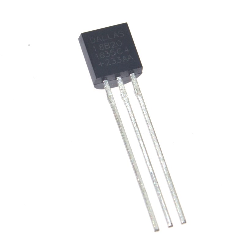
Dallas DS18B20 TO-92 Temperature sensor
All the boards, including the QuinLED-Dig-Uno have a spot for a Dallas DS18B20 TO-92 temperature sensor. It’s a cheap way to add a little sensor to the board!
- 1x Dallas DS18B20 TO-92 temperature sensor
Level Shifter
The ESP8266 & ESP32 natively operates at 3.3v but the Digital Addressable LED strips expect 5v for their input logic signals. Often, sending 3.3v will work but if you start using longer cable runs or longer LED strips, errors can start to show up. Feeding a correct 5v fixes these issues!
(Although in theory you could leave them off the board and bridge the right pins I advise placing the level shifter and have it work correct in all cases. The level shifter method is also best compatible with other type of LED strip such as WS2815, APA102 or SK6812.) (I am aware of the “Donor pixel” method for ws2812b but this is not universally compatible with other type of LED strips)
The variant used (74AHCT125N in a DIP14 package) is suited for high speed switching which is required for APA102 LED strip for instance. Both the Data lines and the Clock lines are fed through the level shifter! They are cheap if you buy them in packs of 10. The DIP14 package also means they can be easily soldered directly to the board or if you so desire can be placed into a socket.
*These shifters are uni-directional, you cannot connect switches or anything else that sends input or expects 2 way communication back to the board on these channels! The broken out external GPIO pins on the board do not have this limitation.
- 1x 74AHCT125N DIP14 Level Shifter
![]() 74AHCT125N Level Shifter (Shopping links have different amounts!)
74AHCT125N Level Shifter (Shopping links have different amounts!)
(The Aliexpress link is for 20, if you need less take a look at the following mouser listing. If that also doesn’t work for you, you can also find them on Ebay)
–update 2019-12-26
Although the AHCT is better (it’s faster) if you can’t find it in stock or want to save a little bit of money the non-“a” version works well for ws2812b, sk6812 and the likes. If you want to run APA102 or similar LED strip I still advise to get the “A” version!

Large Capacitors
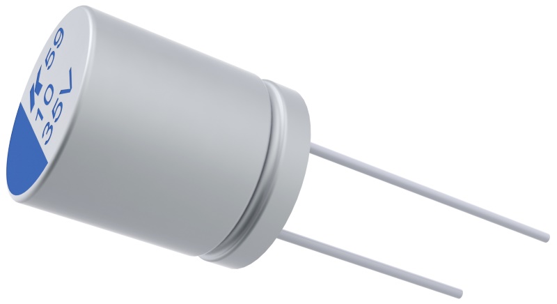
Although everything will actually work without these big caps they serve 2 goals. The first is to limit inrush current into the LED strips which can sometimes damage the LEDs logic chips and second is to stabilize power when different amounts of current is needed because of very rapid color changes, the large capacitors will be able to smooth the demand a bit and help your power supply out, taking the big hits and keeping the LED strip bright and constant whatever the pattern!
The board has two spots for these big capacitors. However because of the design one of them is slightly under the microcontroller while the other one doesn’t have a height restriction. For the one under the microcontroller you need to make sure it’s not higher than 1CM (8mmx8mm works best). The other one has a mounting size of 10mm and as mentioned does not have a height restriction.
5v only or 5v/12v compatible?
You need to choose the appropriate capacitor for the voltage you will use the board for. For 5v only boards you can use 6.3v capacitors but for 12v boards you need 16v capacitors.
The listed capacitors below are good examples which I have tested and work, they are however examples and you can mix and match any capacitor you’d like as long as you adhere to the size restraints. (8mm x 8mm and 10mm x ??mm). I liking mixing a lower value and a higher value. 🙂
If you cannot source the 8mm capacitor you can leave it off, adding the 10mm capacitor is highly recommended though!
5v only
When the board will only be used for 5v buying 6.3v capacitors is fine and I suggest using the following:
- 1x 8mm max 1CM height: 1x 16v 270uF capacitor
- 1x 10mm free height: 1x 6.3v 3300uF capacitor
![]()
10Pcs 8mm x 8mm (height) 16v 270uF capacitors
–Update 2019-06-26 If these small 16v capacitors run out, check here for some alternatives
![]()
10Pcs 10x 25mm (height) 6.3v 3300uF capacitors
5v/12v Selectable
When the board will also be used with 12v LED strip you need to make sure that all capacitors used can handle this. Because of that reason I suggest using 16v capacitors
- 1x 8mm max 1CM height: 1x 16v 270uF capacitor
- 1x 10mm free height: 1x 16v 1500uF capacitor
![]()
10Pcs 8mm x 8mm (height) 16v 270uF capacitors
–Update 2019-06-26 If these small 16v capacitors run out, check here for some alternatives
![]()
10Pcs 10mm x 20mm (height) 16v 1500uF capacitors
SMD Diodes
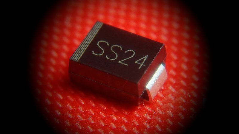
The QuinLED-Dig-Uno has several diodes on board. These serve 2 purposes, there is a diode in parallel with both the input terminals and the output terminals. Combined with the fuse these should help in reverse polarity situations (it should blow the fuse before damaging onboard components). The second is an inline diode which should prevent the ESP module on the board providing power back to the board through it’s 5v pin. Although this is in place I still not do not advise connecting 5v/12v power + USB at the same time!
These diodes are a lot bigger then on my previous boards to make soldering easier! Tweezers are still recommended though! I have also put little stripes on the board to highlight the orientation.
Do NOT connect both a power supply AND USB at the same time!
In the current design the fuses blocks this, take the ESP module off for the initial flash, later flashing can be done while being inserted into the QuinLED-Dig-Uno using OTA methods
- 1x SS12 diode
- 2x SS24 diode
*You will need a tweezer to put these into place, make sure to check out the tools section!
PCB Fuse holder
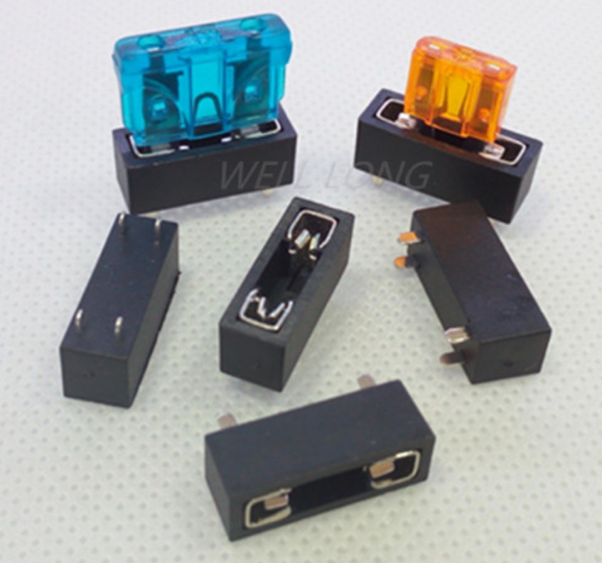
To try and add a bit more “security” to the board I have added an inline fuse holder on the PCB. This holder accepts standard “car” style fuses which are cheap and easy to get in a lot of different values. Take a look at my “what value fuse should I use” (WIP) article to figure out which values you should work with.
- 1x PCB fuse holder
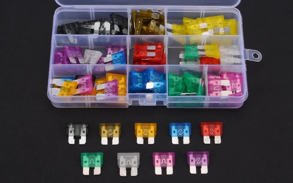
- 1x Assortment of ATO size fuses
(Thes PCB Fuse holders get a lot cheaper when buying in bulk, also check out this link)
Shipping can take very long for this item, you can also find them on Mouser or otherwise maybe Ebay. Or you can try searching for part nr: 3557-2
ATO fuses
Once you have fuse holders you will need some fuses. Again, take a look at my “what value fuse should I use” article. With that said, to start out I recommend getting a assortment kit with lots of different values included.
![]() 1x ATO standard size fuse assortment kit
1x ATO standard size fuse assortment kit
12v DC-DC converter
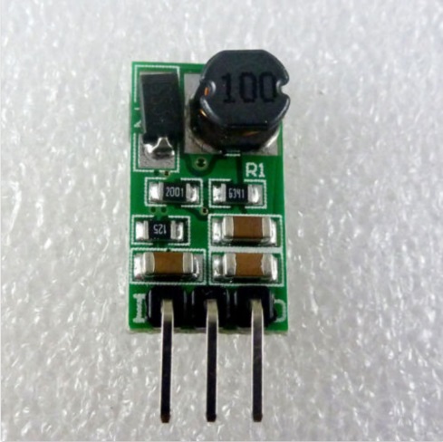
When putting together a 5v/12v board you are going to need a DC-DC converter. This component is NOT needed if you are only going to run 5v. This DC-DC converter is tiny but it does a great job and doesn’t become hot! We are converting 12v to 5v for the onboard electronics. I have tried using the popular 7805 linear regulator but in my opinion any linear regulator will become too hot because it’s convertering 12v down to 5v thus burning off 7v. The switching regulator used does this much more efficiently and thus with a lot less heat.
Sadly they this DC-DC converter is a bit more expensive than others models but nothing else worked in the current design or the board would have to become a lot bigger!
- Optional 12v only component!
- 1x DD4012SA_5v DC-DC Converter
![]() DD4012SA_5V 6v~40v to 5v converter (Get the 5v version, they are A LOT cheaper per 10)
DD4012SA_5V 6v~40v to 5v converter (Get the 5v version, they are A LOT cheaper per 10)
Additional hardware components, tools and equipment
Above are all the components you need to assemble a complete QuinLED-Dig-Uno board! Again, often it’s best to order components for at least 5 boards, soldering doesn’t always go perfect and once you have one self-built Domotica device, it rarely stays at that number.
Also, don’t forget, this article only lists all the components you need, not the tools and other accessories you might also require. Make sure to take a scroll through this article to see what you might also need so you don’t get frustrated if you don’t have it while building! If you still need LED strip check out my article about which addressable LED strips to buy here. And to power it all, check out this article about power supplies!
p.s. If anything listed on here turns out to be wrong or the link has stopped working, please drop me a line using the contact form so I can correct it!

